This thread has been locked.

If you have a related question, please click the "Ask a related question" button in the top right corner. The newly created question will be automatically linked to this question.

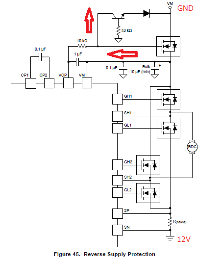
DRV8702-Q1: Reverse Battery Protection Circuit

Part Number: DRV8702-Q1


Dear, Sir.

I would like to make sute the behavior of Reverse battery protection circuit which

is described on DS page 37, figure 45.

I am guessing;

1. Under reverse battery condion, DRV8702-Q1 will start to work, so VCP voltage

    will go up from VM pin voltage. 10kOHM resistor, Transistor & diode is for dischaging

    VCP voltage goes down to turn OFF the external NMOS FET.

    I wonder my understaning is correct?

2. Under Reverse battery condition, the real VM voltage is GND.

    If the voltage is floating, Above protection could be worked correctly?

    Can expect the correct discharging?

Please give your advice.

Best Regards,

H. Sakai

  • Hi Sakai-san,

    1. Under reverse battery condion, DRV8702-Q1 will start to work, so VCP voltage

    will go up from VM pin voltage. 10kOHM resistor, Transistor & diode is for dischaging

    VCP voltage goes down to turn OFF the external NMOS FET.

    I wonder my understaning is correct?

    You are correct.
    There are many paths through the IC and the external FETs that will cause the VCP voltage to go up. If the VCP voltage rises too high, the FET will turn on.

    The 10kOhm, transistor, and diode to discharge the VCP voltage.

    2. Under Reverse battery condition, the real VM voltage is GND.

    If the voltage is floating, Above protection could be worked correctly?

    Can expect the correct discharging?

    If the real VM voltage is floating, the above protection also works because there is no voltage differentials.

    This circuit is used on several of the DRV8xxx EVMs and works.