This thread has been locked.

If you have a related question, please click the "Ask a related question" button in the top right corner. The newly created question will be automatically linked to this question.

DRV8811

Other Parts Discussed in Thread: DRV8811

Hi,

i'm a newbie and i want to drive a bipolar sepper motor (200step-1A) with DRV8811. I have some questions:

  1. In datasheet page 12, at each setp is associated an angle degree...what means?If my motor has an angle equal to 1.8°, i can't drive it at 1.8°resolution?
  2. How can i change motor velocity?

Thanks

  • Aleo -

    No problem, stepper motors can be very confusing!

    In the step table where we are describing an angle, it is actually the ELECTRICAL angle.  Think of it as rotating vectors...

    With your motor that has 1.8 degrees per full step... we divide this 1.8 degree full steps into 360 degrees of "electrical" angle.  As an example, if you full step this motor, you the motor will turn 1.8 degrees per step - that is 360 degrees of electrical "rotation".

    With microstepping, we subdivide the "mechanical" step angle of 1.8 degrees.  So, for example, if you use 1/8 stepping, each "step" is 1.8 / 8 = 0.225 degrees.

    Hopefully that makes sense?

  • Thanks for your answer...

    About electrical angle....reading table i think that 4full steps are divided in 360 electrical angle: so 4*1,8 real angle=360 electrical angle...is right?

    About motor velocity: it can be changed with PWM frequency, right?


  • Yes, sorry, you are correct - the 1.8 degree mechanical step angle is 90 degrees electrical, so 4 mechanical steps per 360 degrees electrical angle.

    The PWM frequency does not change the motor speed.  The step rate is independent of the PWM.  On the DRV8811, you apply pulses to the STEP input.  At each rising edge, the motor will move to the next step (or microstep, depending on the step mode selected).  So you control the motor speed by varying the frequency you apply to the STEP input pin.

  • Thanks for your reply...i have a last question: is it possible to use DRV8811 with micro stepper motor like this

    http://www.globalspec.com/datasheets/2353/micromo/3916A2FF-91E0-4787-83FA-A6DC3110DFB2

    or problems are present?


  • Hi Aleo,

    In essence you could use the DRV8811 to drive the motor as long as the SENSE resistor and the VREF are chosen to supply not more than 200 mA. It may be that the current amplifier is not superbly precise at those very low current levels, but it should be fine. The 3V rating, however, must be ignored as the DRV8811 can only work with anything larger than 12V. Since we are regulating current, the voltage will only define how quick the current increases across the winding component.

    Will this be problematic? Hard to say without more information on the motor. If the inductance is very low, then current regulation may lose tracking as the minimum time off is employed to charge the winding current past the ITrip value on each consecutive cycle. Other than that, I would imagine the motor would operate fine.

    That being said, the optimal solution is a low voltage driver. We expect to have some devices with these characteristics in the upcomming months.

    Best regards,

    JIQ

  • if i use a stepper motor of 7.5 degrees, 12V, 250mA,

    i suppose Itrip= 250mA, therefore Rsense = 3.3/ (8*250mA) = 1.65ohms

    how do i choose C or Toff?

    I did read your blog but still found it a li'l hard to figure out...

    or can i stick to the 47k and 1000pf used on your board for my application?

  • Hi AMJ,

    Your ITRIP equation usage is correct. Do note you can also scale down the VREF input. In fact, it is always better to select the RSENSE first and then the VREF as the available low ohmage resistor valus is not that extensive. Even when there is such a thing as 2512 2W 1.65 Ohm 1% tolerance resistor, actually getting it may be harder than getting a similar but 0.4 ohm resistor.

    Choosing C and R may be a daunting task. You are welcome to use the 47K and the 1000 pf defaulted on our EVM's as chances are it will work. However, the question you must ask is "Will this work as I want?" Choosing the C and the R poorly may result in audible noise. Do you care about this? If you are in a factory floor with hundreds of different motors to the point in which even the floor trembles, why would you care this stepper has an audible high pitch squealing? At that point in time, the audible noise induced by the low frequency of the current regulation is literally in the noise!

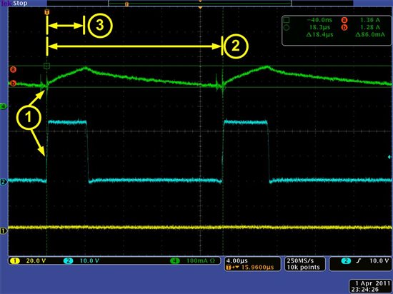
    But if you are in an office and the nearby printer hum is bugging you, then it is time to increase the chopped current frequency to something larger so that frequency components lie above audible range. This is hard to understand unless you are actually seeing the current regulation with a current probe. So here is how it looks:

    Notice a few things on the capture above, where CH1 and CH2 are the H Bridge's output and CH4 is the actual winding current.

    Spot #1: When the H Bridge is enabled, there is a little blip on the current. This is due to the internal switching of the FETs and the body diode conduction during dead time. If this current increase were to be taken into consideration, it could trick the H Bridge into believing an ITRIP event had taken place when in reality this is not actual winding current, but noise caused by parasitc effects. Hence, we must ignore it and the mechanism to do so is called TBLANK. On the DRV8811, TBLANK is selected with the C component at the RCx pin. (TBLANK = 1400 * C) With a C equal to 1000 pf, we have a TBLANK of 1.4 us. This is plenty of time to ignore these current bursts which in fact measure anywhere in the vecinity of 200 to 400 ns.

    But the question was about TOFF. How do I select it? What you truly want to answer is how much is my frequency or the inverse of the time measured on SPOT 2. The higher the frequency, the less audible the motor current chopping is. The higher this frequency, the higher the power losses are as well, so don't make it too large.

    However, the current chopping period is a function of TON and TOFF. TON is portrayed by SPOT#3 and TOFF is the remainder of SPOT#2 - SPOT#3. TON you may not be able to control. It is given by the motor inductance and the application voltage (VM). In this case, my voltage was 24V and the motor inductance is something as given by the motor I was using at the moment of this capture. I don't know this value but I can easily measure it. Regardless, once chosen it is pretty much set in stone. Se we can say the TON is fixed by the application and you can not play with it to adjust the final switching frequency. What we can change is TOFF!

    We know TOFF will be defined by R*C. Once you know your TON and the frequency you want, you can determine what TOFF you will need to obtain. Per example, say you want 50 KHz switching frequency and you know TON is about 4 us. For 50 KHz, the total period is 20 us (1/50KHz = 20 us) and with TON equal to 4 us, TOFF must be 16 us. But you already have selected C as 1000 pf, so you can now determine R as 16us/1000 pf = 16K. So a 16K or close resistor will take you close to 50 KHz for this particular motor. The same exercise can be made for different frequencies such as 40 KHz, or 32 KHz, etc.

    I would try to chose anything in between 30 KHz to 50 KHz and do note it is not crucial to select this value with the uttermost precision. Although you can claim the switching frequency modifies torque response somewhat (which it does as it is a clear modulation on the magnetic field), the implications are so negligible when compared to everything else going on with the system, that to worry about this is pretty much a waste of time and resources. So whether your frequency is 35 KHz in one system and 37 KHz in another, chances are you will not be able to see a notable difference in motion quality. You may be able to see slightly more switching losses on the 37 KHz one, but even this wll be quite negligible.

    Note that once you change the motor (the motor inductance changes, hence the L changes, hence the Ldi/dt changes) or the power supply voltage (VM), you will by definition change the TON which will alter the TOFF requirement. Without changing compoenents, your resulting chopping frequency will change as well. Whether you need to change the R's and the C's will depend on whether the resulting frequency is acceptable or not.

    Usually, when you have a particular design, you will tailor the RC selection to that design. If you have a universal design (one for many motors and many power supply voltages), then you will select something in between and hopefully the user will not mind about the possibly existing audible noise. In that case, it would be hard to please everybody. You could put a potentiometer instead of a fixed resistor at the RCx pins, but that would add tuning which some customers may not appreciate as both H Bridges would need to be fairly similar. I really don't think it would be worth the trouble.

    Hope the info helps. Best regards,

    JIQ

  • WOW :) tat must have taken a lot of patience...


    you said, once i know my TON and frequency, i can determine TOFF....True!

    but how do i know the switching frequency and TON? can i choose any value between 30 and 50 kHz...and what abt TON?

  • Hi AMJ,

    The switching frequency you just choose almost arbitrarily. Out of experience, I know that frequencies in between 30 KHz and 50 KHz will work fine for most applications. This is because the audible range for the great majority of us stops at around 20 KHz.

    Here are some rules of thumb often used to determine whether you want to increase or decrease the frequency:

    1. If the stepper is giving you too much audible noise, the fix revolving around frequency would be to increase said frequency. To how much? It will depend on the application. There are just too many factors and aspects to detail in this message (and have to do with decay mode as in fast versus slow, mixed decay ratio if using mixed decay, motor inductance, power supply voltage, etc.).

    2. The problem with increasing switching frequency is that you increase switching losses as well. FETs loose power through conduction (I^2*R) and by switching (I*V multiplied by the amount of time during the transient curve). Although we make the transient time as short as possible (it can not be too short or other problems arise), there will always be some switching losses. Hence, the more we are switching the FETs, the larger these losses are. If you think your device'e power dissipation is too high, you can try to decrease it a little bit by decreasing switching frequency. In real life, however, this venue is hardly ever utilized as the amount of power dissipation due to switching is considerably smaller than the amount of power due to conduction. So unless your switching frequency is in the hundreds of KHz (200 KHz, 500 KHz, etc), then there is not much you can buy  by reducing the frequency.

    So just pick a frequency in between 30 KHz and 50 KHz. Chances are it will not matter which one you get as long as it is in between this range. But if it becomes an issue for either audible noise or power dissipation, then you can modify it accordingly.

    Now, the TON can not be chosen arbitrarily. In fact, chances are there is not much you can do. TON will be directly proportional to VM, motor inductance and motor speed. Since the application defines all of these parameters, there is not much play area. For example, your application may be 12V or 24V. Hardly ever do you get a variable voltage rail to operate your motors. So, this parameter is defined since the beginning.

    In the same fashion, motor inductance is also chosen by the application as the motor is usually chosen for its torque/speed characteristics which are application driven. There might be a few motors offering the same mechanical mounting hardware and torque/speed characterics, but you will not be able to browse for a motor on an inductance basis.

    Then it depends at what speed the motor is rotating as this will start to introduce a component of Back EMF (BEMF). A motor moving at 1000 Steps Per Second will have larger BEMF than the exact same motor moving at 10 steps per second. Hence, the Ldi/dt is a variable that is mostly out of your hands.

    Like I said, there is not much you can do with the TON as this will be mostly defined by the application. The only variable you can play with is the TOFF which will then define the frequency.

    Hope the info helps. Best regards,

    JIQ