Other Parts Discussed in Thread: DRV8353, CSD19506KTT
Hi
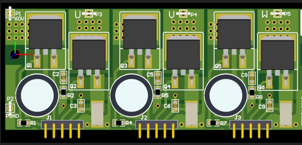
We have designed a motor driver board based on the DRV8353RH-EVM_Sch from TI.
The boards all work fine for low PWM speed demands for forward and reverse rotations of about 500 RPM. We have had them working for several hours at low speed demand.
But when we increase the PWM demand to speed the motor above 500 RPM to 1000 RPM the DRV8253RH chip gets very hot in about 5 seconds and the board stops working permanently. Same is true if we do rapid forward and reverse rotation in this case the DRV8353 chip gets very hot in less than 3 seconds and the board stops working.
We have a fault LED on the fault pin and this comes on. After we power down the board and power up again the fault LED comes on straight away indicating there is a fault.
The damage always seems to be between one of the GLx & SPx pins which shows a resistance of less than 10R (should be 140K according to the datasheet). We measured this with the Mosfet de-soldered off the board, because at first we thought the Mosfet had gone short circuit but this is never the case.
We have checked the Mosfet's they are fine and working. The DRV8353RH chip always stops working after a high PWM demand and the board has to be scrapped. We have now gone through 5 boards during our pre-production testing.
The board is powered from a 36V supply and everything on the board is rated to at least 80V or above.
During our motor board testing the power supply current never goes above 1.5A maximum when the motor is driven.
We have tried the motor driver board with the DRV8353RH Pin 5 (VM) with both 12V independant input as well as 36V option connected to the motor supply. It makes no diiference to the chips permanently being damaged on the board.
We use 3 x PWM input into the DRV8353RH chip. INLx Pins 35,37,39 are tied to +5V(as in the datasheet) and INHx Pins 34,36,38 are driven by the PWM signals.
The IDRIVE is selectable through a 7-way rotary switch from 50mA to 1A (we use 450mA any less the motor does not move unless a very high PWM demand is given to the motor).
The VDS is selectable through a 7-way rotary switch from 60mV to 1V and is set at 200mV to trip.
I have checked our schematic against the eval board and they are identical in the connectivity apart from the 3 x PWM signal inputs we use in for our software. This PWM software has been working for over 10 years in our older design with no problem and we were using an older driver chip before.
Can TI shed any light as why the DRV8353RH chip should so easily fail?
Any help would be appreciated.
Thank you
Minesh