Dear experts,
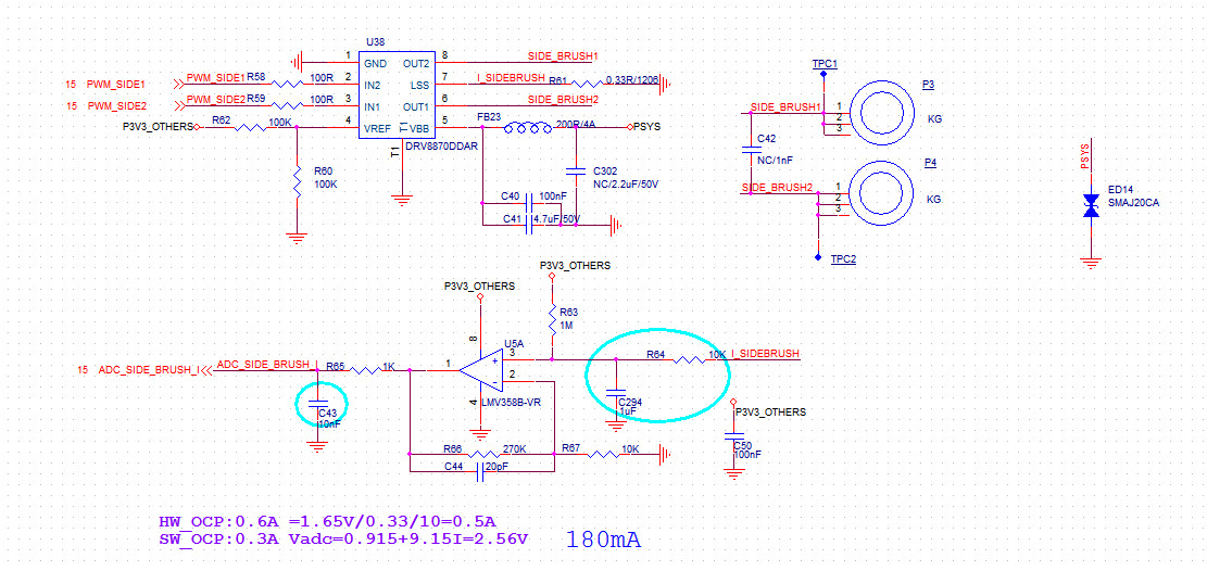
My customer is testing OCP function of DRV8870. They applied PWM signal to IN1 and set IN2 to high, when short OUT1 to OUT2 they find OUT1 and OUT2 remain high. It's strange because it seems that high side FETs are conducted but all FETs should be disabled based on datasheet. And it didn't resume or repeat fault cycle. Could you help to explain the question, or maybe it triggered another protection?
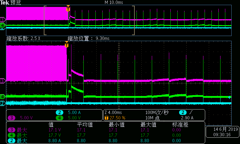
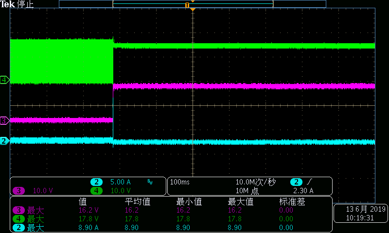
CH2:current of OUT1 terminal; CH3:OUT1; CH4: OUT2.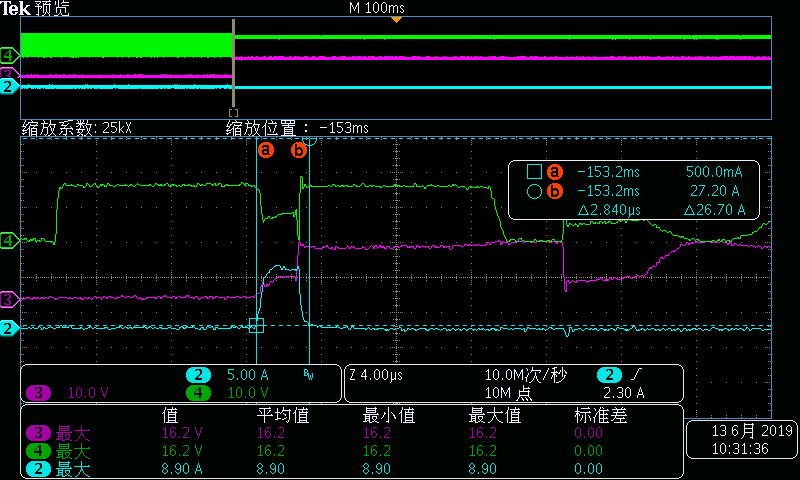 CH4:OUT2
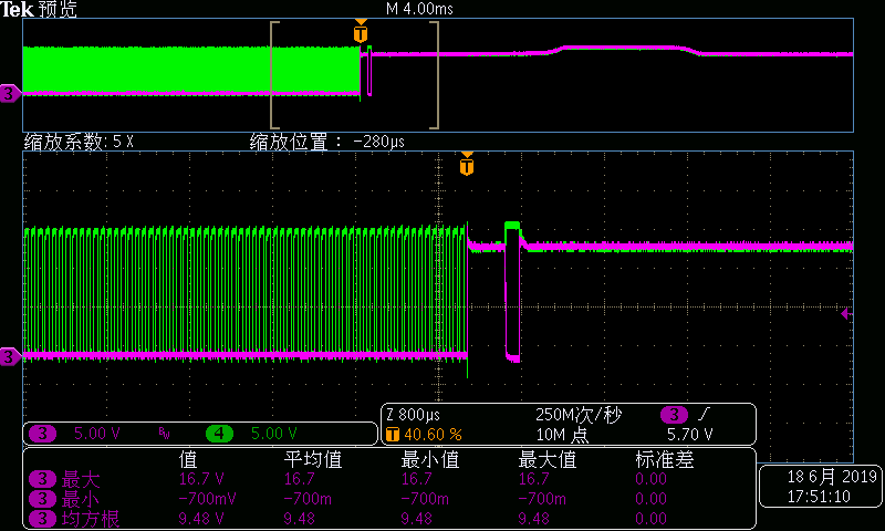
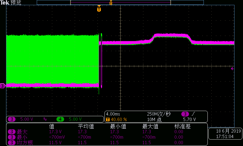