This thread has been locked.

If you have a related question, please click the "Ask a related question" button in the top right corner. The newly created question will be automatically linked to this question.

DRV8844: Unexpected Failure during short test

Part Number: DRV8844

Hi, Team

Customer reported IC failure when doing outputs direct short test on DRV8844.

DRV8844 is plugged to +/-24V power supply and drive 4 bi-directional solenoids.

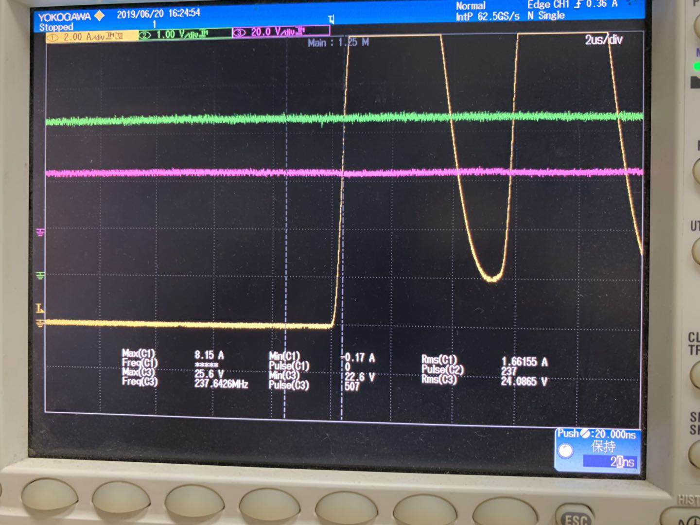
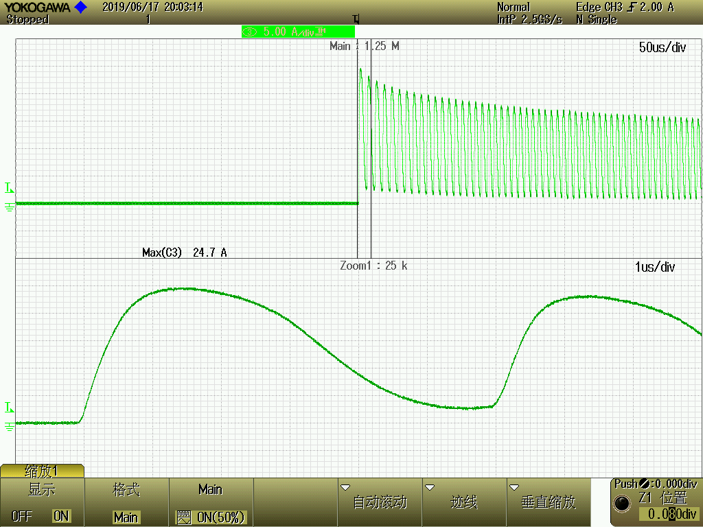
>20A peak current was captured from current waveform. IC was damaged. OCP not triggered.

Is there analog current limitation to avoid IC damage from inrush current?

Other than limit the current from power supply, any other suggestion we may offer to avoid failures?

  • Hi Alvin,

    I have a quick question. Are the current waveforms displaying the power supply input current or the output current?

  • Hi Alvin,

    In addition to Pablo's question, we have a few more.

    1) What is the input PWM rate?

    2) What is the input duty cycle?

    3) Would you please confirm the grid in images 2 and 3? Do 10 minor vertical grids make up the 50us/div and 1us/div?  For example, does the current in image 2 reach ~24A in ~1.6us? in the 1us/div zoom in?

  • Hi Pablo and Rick,

    This issue was reported by my customer. I can answer your questions:

    1. The current is output current from OUT pin of DRV8844.

    2. The test was done with DC input, no PWM signal. The test was done in this way: 1. Disable DRV8844 by setting ENx=0, and shorting corresponding OUTx to GND; 2. Enabling DRV8844 with INx=1 (for shorting to +24V testing) or INx=0 (for shorting to -24V testing). The device can survive if INx=0 (shorting to -24V, since VM=+24V, VNEG=-24V), FAULT signal triggered properly. While the device was burned if INx=1, without any FAULT signaling.

    3. During shorting condition, the voltage on VM pin (+24v) and V3P3OUT (3.3v) kept fairly stable in spite of OUT current dramatically fluctuated between 0 and 24A.

    4. FAULT output always high until the part was destroyed.

    5. About the grid in images 2 and 3: 5 minor vertical grids make up 1us (1us/div, each div includes 5 minor grids).

    Thank you!

    John

  • Hi John,

    Thank you for the additional information.

    What is causing the current to decrease and increase as shown?

    This could be a contributing factor because the OCP deglitch time (Tocp) may not be met.

    If the OCP deglitch time is not met, the outputs will continue as shown.

    What does the current during the INx=0 short (shorting to -24V) look like on the scope?

  • Hi Rick,

    I don’t know. But surely it’s not due to the load, which is a simply wire connecting OUT to GND. Also we cannot due the reason to power supply, which is very stable during shorting test. Also, through the image I sent you can find, the time for output current exceeding OCP threshold has significantly longer than deglitch time. It is almost 8us for Iout >5A.

    Thank you.

    John

  • Hi, Rick

    I sent you the test report through mail.

    We have no clue how current vary that much. As the outputs are directly shorted through wire, and power supply has big enough capability to supply constant >20A.

    One concern is can DRV8844 survive with >24A inrush current? 

  • Hi Rick,

    The current during shorting to -24V please see the report Alvin sent you. The waveform is similar but only one pulse, no multiple repeat. A difference between +/-24V power supply is power capacity. The power of +24V is high enough that keeps VM stable during short condition, while -24V may be pulled down significantly during short to -24V (the waveform of VNEG was not included in test report.).

    Thank you,

    John

  • Hi John and Alvin,

    Thank you for the additional information. I cannot explain why the current is decreasing then increasing as shown when the output is shorted to GND. I will discuss this with the design team.

    OCP may not assert at 5A. Per the datasheet, 5A is a typical value. OCP could assert as low as 3A, or higher than 5A.
    When an OCP event occurs, the current is expected to be consistently higher than the OCP trip level. The current oscillation is not expected.

    I should have a response by Friday.

    While waiting, if you determine the reason for the current increasing and decreasing please let us know.

    Please confirm the VM was measured at the DRV8844 pins as stated. If not measured at the pins, please provide scope captures of VM at the pins.

    Also please provide the VCP, VNEG, and the OUTx voltage when this is occurring in another scope capture.

  • Hi John and Alvin,

    The designer would also like to see LGND. Ideally, he would like to see the ENx pin measured differentially with respect to the LGND pin.

    Can you also provide this scope capture?

  • Hi Alvin,

    We will send some additional information, but it appears the LGND is bouncing in the case above.

    This could cause ENx to change from a logic high to a logic low, disabling the output. When the output is disabled, the current decreases and ENx is seen as a logic high again. The cycle repeats until the device is damaged.

    This thread will be marked as "TI thinks resolved", but please reply if you have further questions.