This thread has been locked.

If you have a related question, please click the "Ask a related question" button in the top right corner. The newly created question will be automatically linked to this question.

DRV2605L-Q1: About configuration of DRV2605/DRV2700

Part Number: DRV2605L-Q1
Other Parts Discussed in Thread: DRV2700

Hi team,


A customer uses DRV2605L-Q1 and DRV2700 to drive piezo actuator. Can you answer the following questions?


  1. DRV2605L-Q1 is used as an input to the DRV2700. With the internal libraries waveforms of DRV2605L-Q1, is it possible to driver piezo actuator through DRV2700?

  2. Can you share the waveform document for the effect 1~123 in ROM library?

  3. When the GO bit in register 0x0C is asserted, Playback begins. BTW, does it output the waveforms in the queues repeatedly until the GO bit is de-asserted? Otherwise, should user set the GO bit after a cycle for the continued playback?

  4. Can you check if the following sequence is okay?

    1) 2700 Gain0, 1 init : (0,0)

    2) 2700 EN -> high

    3) 2605 EN -> high

    4) 2605 mode : remove from stanby mode

    5) 2605 auto calibration register settings (rated voltage/overdrive voltage clamp/Feedback/control 1,2,3,4)
    6) 2605 set go bit : start auto calibration

    7) 2605 ERM lib init (ERM / open loop / internal trigger)

    8) 2605 Select library : ERM A

    9) 2605 Select waveform index : 0x04~

    10) 2605 Set Go bit : fire the process

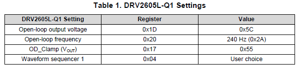
  5. In addition to below settings, are there any specific settings of DRV2605L-Q1 for the input of DRV2700?


      6.   Do you have an example code?

Thanks,

Sam Lee

  • Hi, Sam,

    1.- In order to use the internal libraries with the DRV2700, the DRV2605L-Q1 would need to be configured in open-loop mode. All the configurations that involve an output feedback (closed-loop, auto-calibration) cannot be used in this case since the load would not be an LRA or ERM (which are the only loads supported by the DRV2605L-Q1). Open-loop mode offers the possibility to adjust the output voltage and the frequency (if required). In that case, the DRV2605L-Q1 could output a signal from the libraries in PWM format.

    Then, the output would need to be connected through an RC filter to the DRV2700 as shown in the figure 33 of datasheet ( http://www.ti.com/lit/ds/symlink/drv2700.pdf#page=21 ).

    However, this is not a common usage of the haptics drivers and we would recommend to use another PWM source instead of the DRV2605-L. 

    2.- Could you contact me via email in order to provide the details of the ROM library?

    3.- Once the GO bit is enabled, the DRV2605L-Q1 may generate up to 8 waveforms in sequential playback. The GO bit will be disabled once the sequence finishes. So, the user would need to send GO commands constantly for a constant waveforms generation.

    4.- All the registers sequence is correct except the lines that involve the auto-calibration. As I mentioned, it could result in an error since the load won't be an ERM or LRA. The open-loop would be needed.

    5.- You may take a look at the example below for details about the effect generation in open-loop mode.

    Exported at :7/5/2019 12:24:02 PM
    	========Register Dump Start========
    		Reg:[0x0]	=	0xe4		Status
    		Reg:[0x1]	=	0x0		Mode
    		Reg:[0x2]	=	0x0		Real-Time Playback Input
    		Reg:[0x3]	=	0x1		Library Selection
    		Reg:[0x4]	=	0x1b		Waveform Sequencer 1
    		Reg:[0x5]	=	0x0		Waveform Sequencer 2
    		Reg:[0x6]	=	0x0		Waveform Sequencer 3
    		Reg:[0x7]	=	0x0		Waveform Sequencer 4
    		Reg:[0x8]	=	0x0		Waveform Sequencer 5
    		Reg:[0x9]	=	0x0		Waveform Sequencer 6
    		Reg:[0xa]	=	0x0		Waveform Sequencer 7
    		Reg:[0xb]	=	0x0		Waveform Sequencer 8
    		Reg:[0xc]	=	0x0		GO
    		Reg:[0xd]	=	0x0		OverDrive Time Offset
    		Reg:[0xe]	=	0x0		Sustain Time Offset, Positive
    		Reg:[0xf]	=	0x0		Sustain Time Offset, Negative
    		Reg:[0x10]	=	0x0		Break Time Offset
    		Reg:[0x11]	=	0x5		Audio-to-Vibe Control
    		Reg:[0x12]	=	0x19		Audio-to-Vibe Minimum Input Level
    		Reg:[0x13]	=	0x64		Audio-to-Vibe Maximum Input Level
    		Reg:[0x14]	=	0x19		Audio-to-Vibe Minimum Output Drive
    		Reg:[0x15]	=	0xff		Audio-to-Vibe Maximum Output Drive
    		Reg:[0x16]	=	0x53		Rated Voltage
    		Reg:[0x17]	=	0xa4		Overdrive Clamp Voltage
    		Reg:[0x18]	=	0x6		Auto Calibration Compensation Result
    		Reg:[0x19]	=	0xf2		Auto Calibration Back-EMF Result
    		Reg:[0x1a]	=	0x27		Feedback Control
    		Reg:[0x1b]	=	0x93		Control1
    		Reg:[0x1c]	=	0xf5		Control2
    		Reg:[0x1d]	=	0xa1		Control3
    		Reg:[0x1e]	=	0x20		Control4
    		Reg:[0x1f]	=	0x40		Control5
    		Reg:[0x20]	=	0x30		LRA Open Loop Period
    		Reg:[0x21]	=	0xce		VBAT Voltage Monitor
    		Reg:[0x22]	=	0x36		LRA Resonance Period
    	========Register Dump End========
    

    Please let me know if you have additional questions or comments on this.

    Best regards,
    Luis Fernando Rodríguez S.