This thread has been locked.

If you have a related question, please click the "Ask a related question" button in the top right corner. The newly created question will be automatically linked to this question.

DRV8829EVM: About the problem of output current.

Guru 11255 points
Part Number: DRV8829EVM
Other Parts Discussed in Thread: DRV8829, DRV8329

Hi team.

I use an external MCU to control DRV8829.

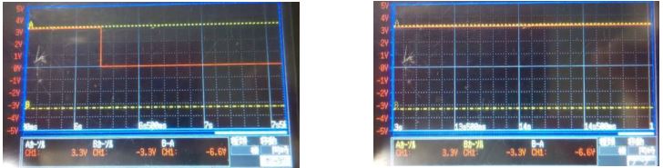
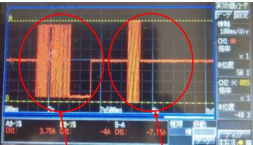
When Vref is input 2.2V(I think output is 4.4A), no output from one of the drivers.

The other driver output about 4A.

Vref was supplied by the same voltage source.

 Why is it not output?

However, when Vref is 1.5V and other, both are output.

Sincerely.

Kengo.

  • Hi Kengo-san,

    What modifications have been made to the EVM to allow external control?

    Are you monitoring nFAULT on the driver with no output? If nFAULT is low, what is required to remove the fault?

    Cycling nSLEEP?
    cycling nRESET?
    cycling power?

    Can you provide the voltages or a scope capture of the following signals of the no output device:

    nFAULT
    V3P3OUT
    VREF
    ENABLE
    PHASE
    nSLEEP
    nRESET
    OUT1
    OUT2

  • Hi Rick-san.

    Thank you for your reply.

    Yes, nFAULT is Low. but another device is high.

    I will get the wave form you say.

    Please let me know if there is a reason for only one nFAULT is Low.

    Sincerely.

    Kengo.

  • Hi Kengo-san,

    The information requested should help determine the reason.

    Please refer to section 7.3.4 of the datasheet.

    The operation of the nFAULT helps determine the type of fault being seen. For example, overcurrent disables the device until action is taken. Thermal shutdown and undervoltage recover automatically.

  • Hi Rick-san.

    It's exactly you say.

    However I think if it is OCP, another device should be same.

    Our phenomenon is only one of two DRV8329 on same EVM.

    And then, DRV8329's OCP is 6A.

    Sincerely.

    Kengo.

  • Hi Rick-san.

    I got some wave form.

    Could you check our phenomenon.

    All images are A on the left and B on the right.

    Then all are the waveforms when driving.

    *A is disabled because it is faulted.

    nFAULT


    V3P3OUT

    VREF

    The input is the same.

    ENABLE


    PHASE

    OUT1


    OUT2

    Sincerely.

    Kengo.

  • Hi Kengo-san,

    This points to an overcurrent.

    If possible, please provide a scope capture of the current of A just prior to the nFAULT occurring.

    Can the customer switch the outputs from A to B and B to A?

    If so, does the fault move to the B device? This could indicate a problem with the load or a difference in the overcurrent operation of the two devices.

  • Hi RIck-san.

    We measured what you said.

    ''Can the customer switch the outputs from A to B and B to A?''

      -> The results is not change. The same driver has become OCP.

    As you say, I think the OCPs of the two devices are different.

    But, according to the data sheet, the OCP is 6A(min to max).

    Does this mean that there is no variation?

    This is the current wabeform that does not output.

    The output will be no output(OCP) in the second waveform.

    Sincerely.

    Kengo.


  • Hi Kengo-san,

    But, according to the data sheet, the OCP is 6A(min to max).

    Does this mean that there is no variation?


    That is a mistake. The 6A minimum is correct, but there should be no maximum stated.

    If the current is above 6A for more than 3.75us (typical), the overcurrent could occur. Device to device variation (Iocp level or tblank) may allow one device to continue to operate while the other does not.

    To confirm this is an OCP event, please zoom in (5us/div) on the nFAULT event to measure the current prior to the event. If the current is >6A for ~3.75us, this is probably an OCP event.

    If the current is <6A, another possibility is one of the two outputs pins is not connected to the PCB.

  • Hi Kengo-san,

    Another approach to determine the difference between the two DRV8829 devices on the EVM is to connect an inductor between the outputs.

    The inductor should have a L/R time constant should be long enough to allow a slow ramp of current.

    The OCP level can be determined by measuring the current approximately 3.75us prior to nFAULT asserting. This should help show that the OCP trip level is >6A.

  • Hi Kengo-san,

    Do you have any further updates from the customer?

  • Kengo-san,

    I am going to close this post. You can re-open it by posting your update.

  • Hi Rick-san.

    I'm sorry for delay reply.

    I got a waveform about this issue.

    Could you check it?

    Please let me know, If you have any something wrong.

    Sincerely.

    Kengo.

  • Hi Rick-san.

    Did you come buck from vacation?

    Could you give me your advice on this issue?

    Sincerely.

    Kengo.

  • Hi Kengo-san,

    Sorry for the delay.

    I do not have a good explanation for the behavior. As you noted, OCP is the most likely reason but the current appears to be below the threshold.

    It is possible there is some damage either on the EVM or the device causing this.

    Do you have another EVM to try?

  • Hi Rick-san

    I got it.

    I will try to evaluate another EVM.

    If there is still problems, I will post another thread.

    Sincerely.

    Kengo.