Hi Adam,
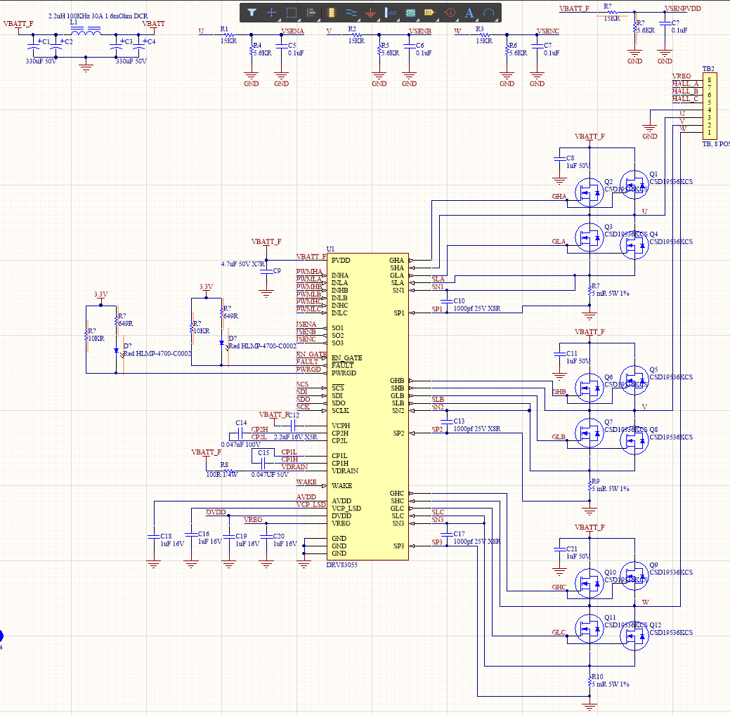
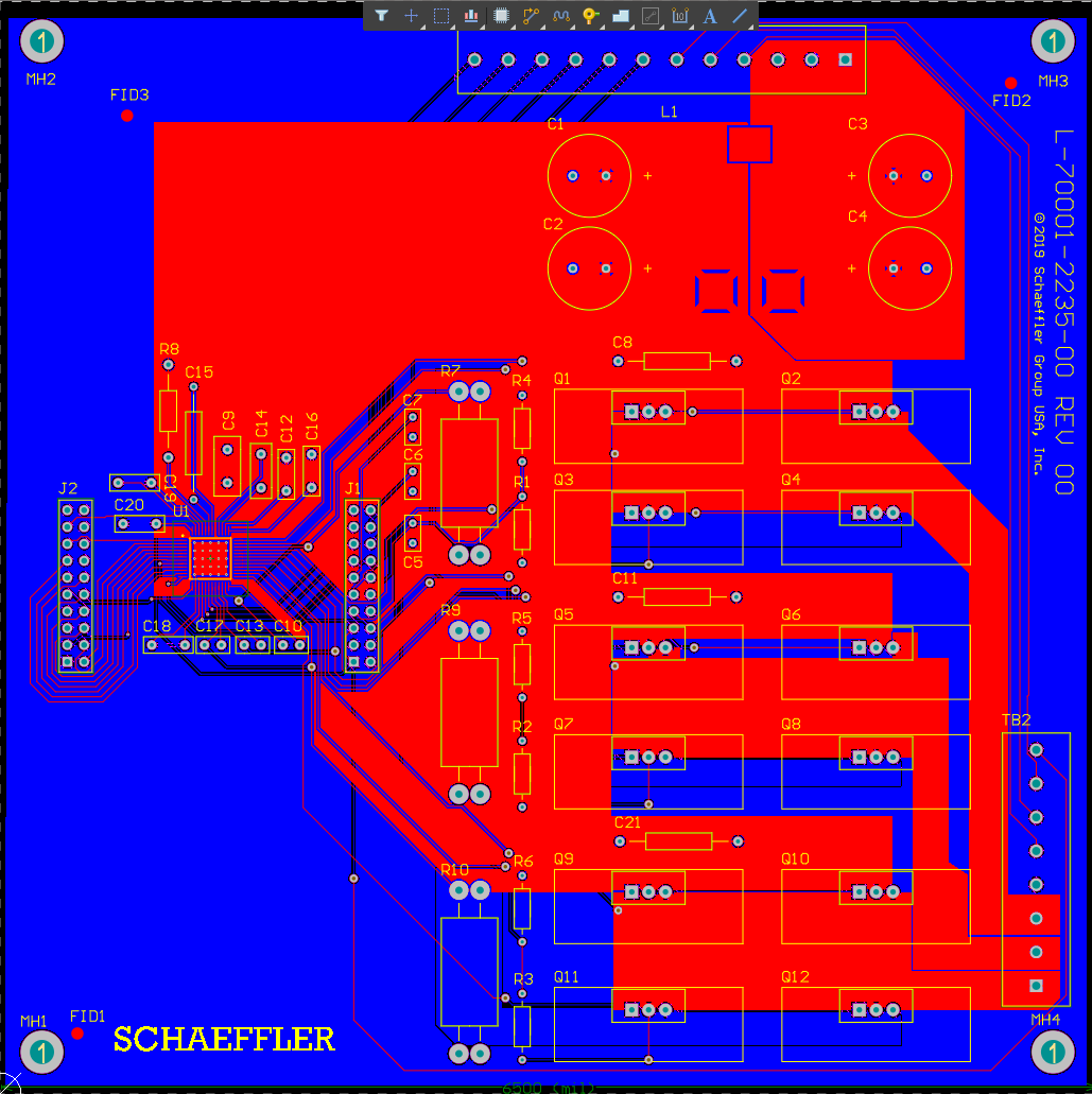
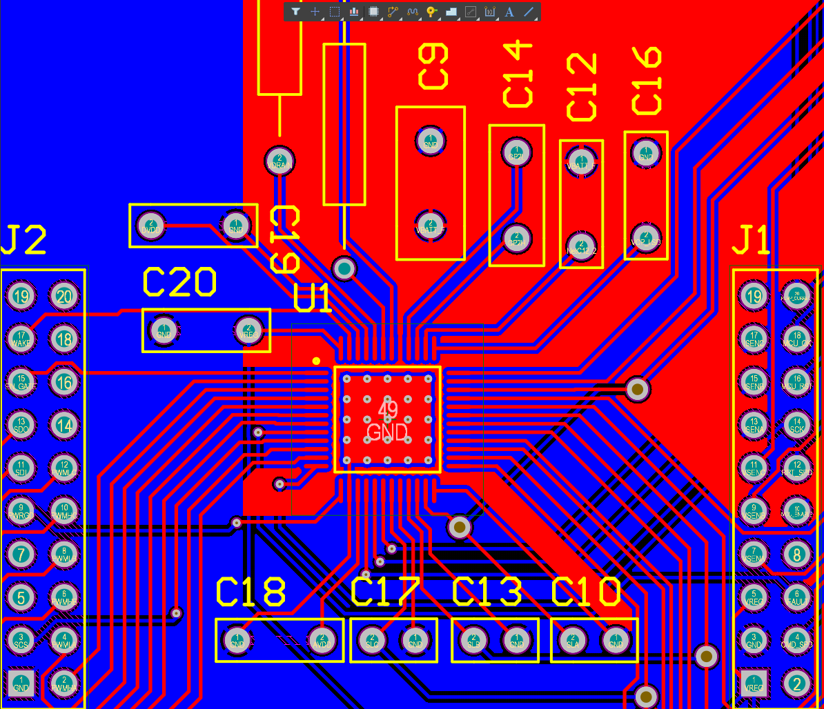
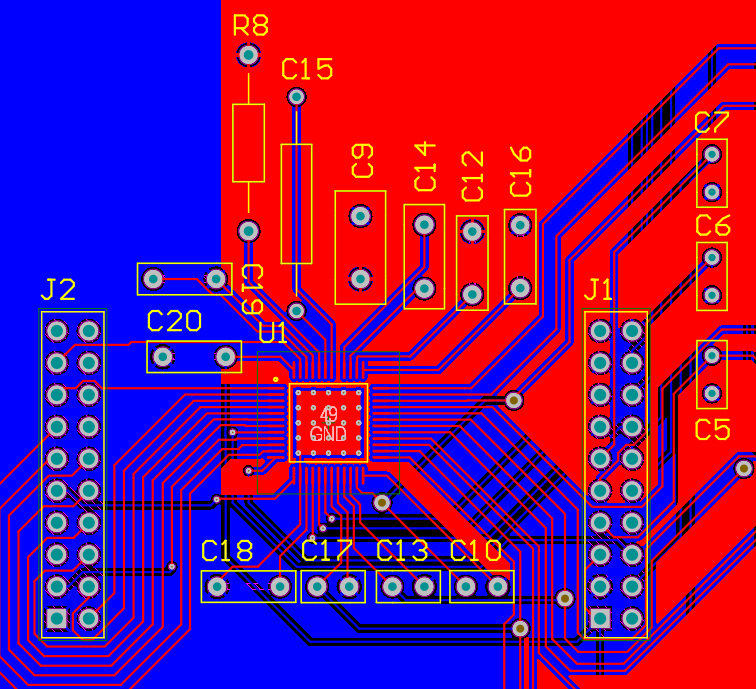
I am replying to this thread with a "related question" to change the status from resolved to not resolved. I posted the schematic and pcb layout yesterday afternoon.
Thanks,
Bob
Hi Adam,
I am replying to this thread with a "related question" to change the status from resolved to not resolved. I posted the schematic and pcb layout yesterday afternoon.
Thanks,
Bob