This thread has been locked.

If you have a related question, please click the "Ask a related question" button in the top right corner. The newly created question will be automatically linked to this question.

DRV2510-Q1: How to Master I2C communicate with the Slave (2510)device

Part Number: DRV2510-Q1

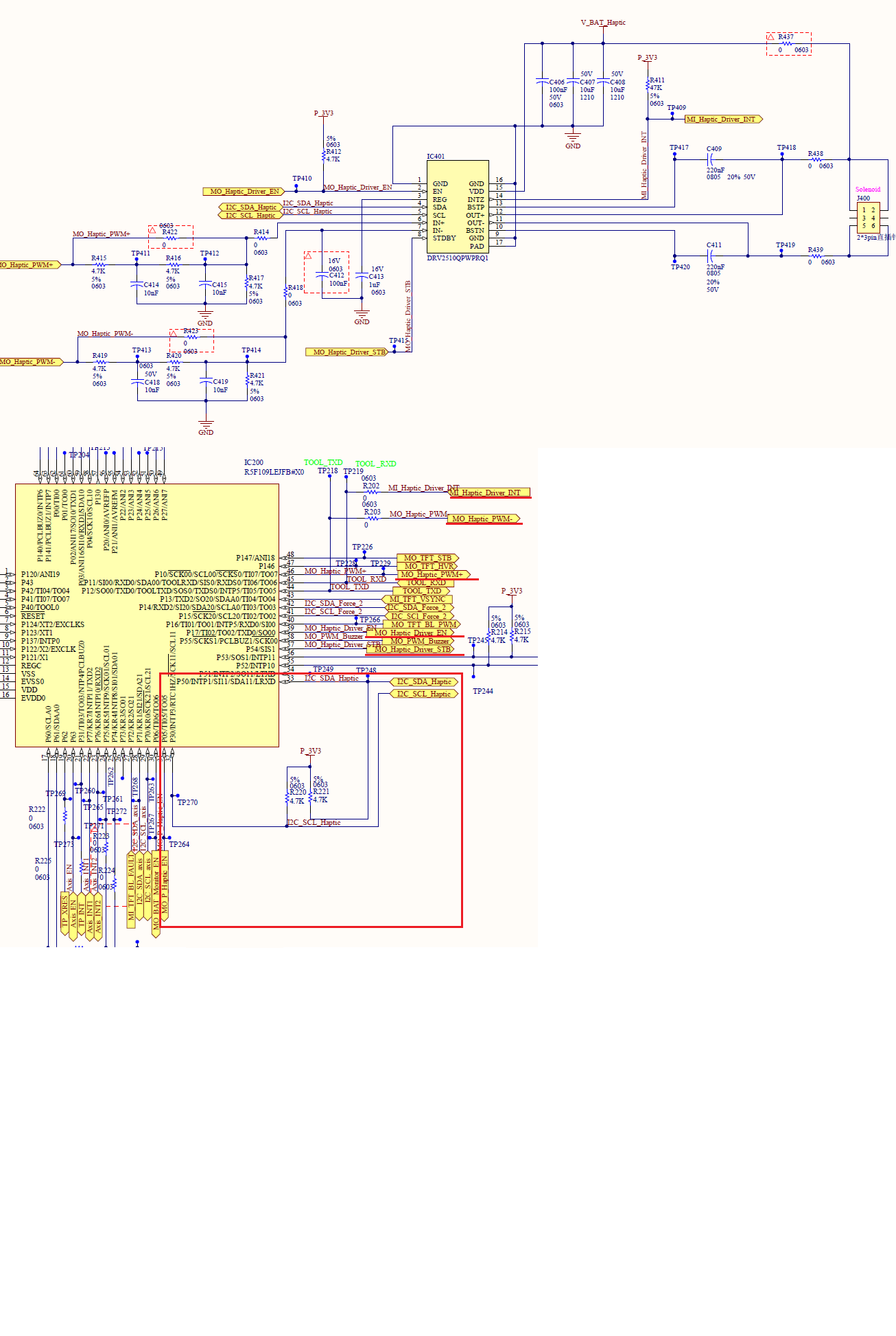
   in drv2510 datasheet :

                 when the power on,  the drv2510 default is shutdown , 

in this mode,   I2C is not operational in this mode and the output is in Hi-Z state.

                 And how to can be shutdown to active mode .

                 Already done:

1.       VDD is Power supply.(12V)

2.        EN is high

3.       STDBY is LOW OR HIGH both Try

4.       The device Motor Run(WHEN IN- IN+ input  the OUT- OUT+ is Output valid)

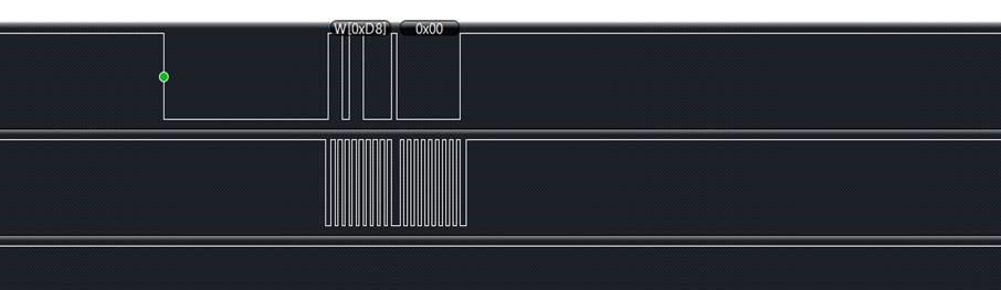
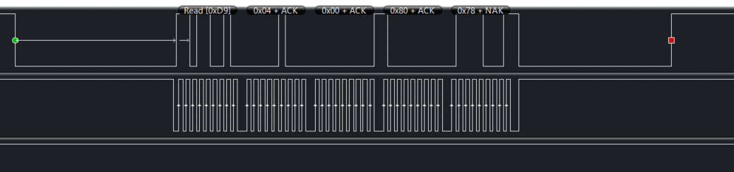
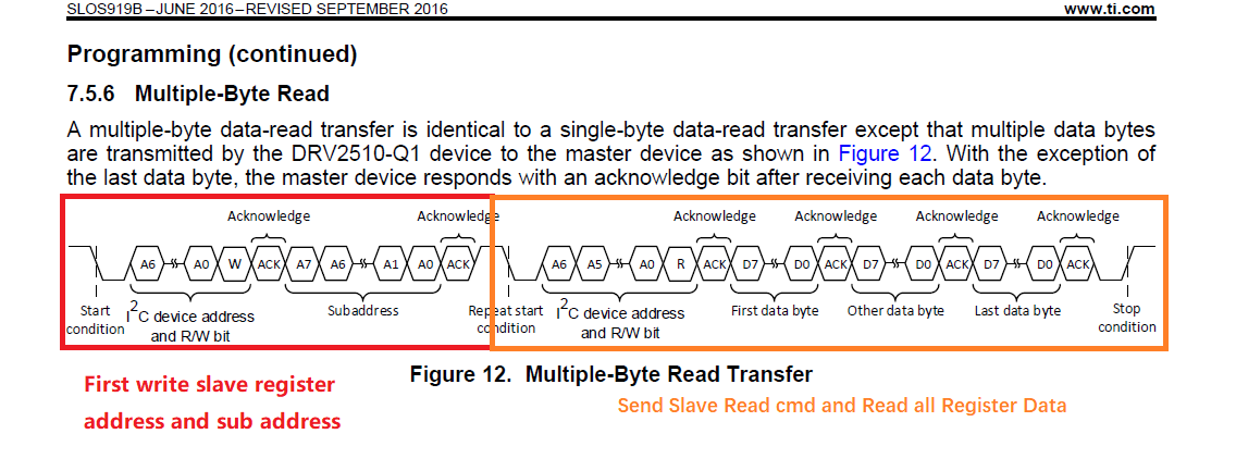
Slave Address is 0x4B

And when I send Master I2C communicate The Slave(2510) can be not ACK response。

  • Hi,

    Could you try with a different slave address, please? 0x4B is not a valid slave address. You should try with 0x5A. Or 0xB4 for writing and 0xB5 for reading.

    Could you also provide your circuit schematic?

    Best regards,
    Luis Fernando Rodríguez S.

  • Thanks for help.

    Sorry,not 4B, write wrong. Have tried B4 write and B5 Read, still I2C not communicate.  PWM output is ok.

    The web can't upload a file.

    MCU is R5F109LE,  pin 32, 33 I2C both with 4.7k pull up Res,   INT, EN  has 4.7k pull up, STB no pull. 

  • Hi, 

    You can use the E2E options in order to attach a file, so we can take a look at your schematic and provide better suggestions. In addition, you may use our E2E chat to share more information personally.

    What voltage level are you using to power the EN pin and the I2C lines? I mean, are the 4.7K pull-up resistors and EN pin tied to 5V or lower?

    Which capacitance value do you have at the I2C lines?

    Could you also try with the I2C slave address 0x6C (7-bit)?

    Best regards,
    Luis Fernando Rodríguez S.

  • Hello,

    Thanks, today  tried 7-bit 0x6C and 2.2k pullup, still can't communicate. All IC power is 3.3V, no caps on I2C.

    The schematic as below.

  • Hello,

    Thank you for providing the schematic circuit.

    Could you try increasing the EN pin pull-up resistor to 100K?

    Have you replaced the DRV2510-Q1 with a new one (just to discard device damages in the current IC that you are using)?

    Have you verified that the microcontroller that you are using is writing the I2C commands according to the datasheet ( http://www.ti.com/lit/ds/symlink/drv2510-q1.pdf#page=12 ).

    Best regards,
    Luis Fernando Rodríguez S. 

  • Hello,

    Excuse me, do you have a feedback on this? Could you take a look at my questions above?

    Best regards,
    Luis Fernando Rodríguez S.

  • Hello,

    Tried 100K for EN pullup, not work.

    The DRV2510 we used is spot buyed, tried another board, still not work.

    The I2C commands is follow the datasheet.

  • Hello,

    One additional question about this issue, when the device is powered on and enabled, can you use the device? I mean, do you have an output signal when the device is powered on? Is the I2C lines the only problem that you have? Is the rest of the circuit working as expected?

    Could you also send a I2C read command capture showing the I2C address, 8-bit register address and the data that you receive from the DRV2510-Q1?

    Best regards,
    Luis Fernando Rodríguez S.

  • Tried no related with EN pull up.

    In the before tried 0x6C without power restarted, can't communicate.

    Now tried 0X6C adress with power restarted, it can comminicate, but only succeeded once at evey power up.

     When Power On , I Can Read The Drv2510 Data , The Frist Read Data is 0x04 0x00 0x80 0x78, And This Data Corresponding register address is 0x00-0x03

     But The I2C communication Read Data : The 0x04 0x00 0x80 The slave response Ack , And  The 0x78 Data The Slave Not response Ack(NAk); Here is NAK, not sure if it is a problem.

     And Then I try To Second Read The Drv251https://e2e.ti.com/cfs-file/__key/communityserver-discussions-components-files/38/DRV2510-SW.7z0 Register Data , I Unable to get response information To The DRV2510.( Sencond communication Fail)

  • Hi,

    Thank you for providing the attached data.

    Regarding the I2C capture that you attached (I2C Wave.png), I noticed that there is a write command for the register 0x00. The register 0x00 is Read-only type. If you omit this write command, do you have the same results? I mean, could you only read the registers from 0x00 to 0x03 or write register 0x03 only? 

    In addition, I don't see the register address selection in the read command waveform. The read command must include a sub-address as shown in section 7.5.5:

    http://www.ti.com/lit/ds/symlink/drv2510-q1.pdf#page=13

    Best regards,
    Luis Fernando Rodríguez S.

  • Hello,

    Can't omit 0x00, it is register adress.

    When I Read Slave Alll Register Data,  Frist Send Slave Write Address Cmd And Subaddress ,Then Send Slave Read Address Cmd. Last Read All Register Data.

  • Hello,

    Thank you for your information above.

    However, it seems that you are sending a write command for a multiple data reading.

    In order to perform a multiple data reading, you must send an I2C read command, then the subaddress. After this, you can perform a multiple-byte reading.

    Could you use a read command instead of the write command?

    Best regards,
    Luis Fernando Rodríguez S.

  • Hello,

    For the progress you mentioned, it not communicated.

    My progress is : white cmd, white adr, read cmd, read adr.  

    In detail, after The Power is On, MCU give EN low for 229ms, then give EN high level.  and Then MCU with Frist i2C communication , and the Slave can be response to MCU including ACK , then after 10 ms, MCU will second  I2C communication, but the slave can not be response.

    so, the question: Why MCU second I2c Communication , slave not response,

  • Hello,

    Thank you for the details on your procedure.

    Could you try increasing the time between the last ACK bit and the second I2C communication? Could you modify it from 10ms to 300ms?

    Please let me know how it results.

    Best regards,
    Luis Fernando Rodríguez S.

  • Hello,

    Excuse me, do you have a feedback on this?

    Best regards,
    Luis Fernando Rodríguez S.

  • Hello,

    Tried 300ms, still NOK for I2C.

    Anyway,  even I2C error, it still have output by inputing wave and using defalt setting like 400kHz. In this condition, we will not take time to investigate the I2C error issue, and plan to use 2511 on our next version board for a higher current drive, meanwhile which has no I2C.