This thread has been locked.

If you have a related question, please click the "Ask a related question" button in the top right corner. The newly created question will be automatically linked to this question.

DRV8308: OCP register Issue

Part Number: DRV8308
Other Parts Discussed in Thread: DRV8305

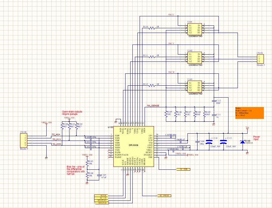
I have a Dual Brushless DC Motor Drive application using an MSP430 and two DRV8308, one driving a 1A motor and the other a 10A motor. I am able to write to the registers over SPI and all seems fine because the both motors runs perfectly. I have configured the ISEN shunt resistors to coincide with 500mV on the OCPTH registers at full current. The application for both motors runs at about 150mV to 200mV during normal running. I can lock the rotor on the smaller motor and the current peaks to 1A, but then drops to around 0.5A (500mV).

I am trying to use the 0x2A register to determine over-current. However, despite reading the register in a loop, I always read 0x18 (UVLO & CPFAIL). I have tried clearing the 0x2A register by writing 0x00, but get the same result. I would like to be able to determine over-current on the motor to ensure the application does not go into locked rotor in the field.

Please can you assist?

  • Warren,

    Have you checked the output of the charge pump and the VM level at the pins of the DRV? We should check if you are in fact getting a UVLO or CP fault.

    These two faults are SET at power-up by default and must be cleared. If there is a true CPFAIL then the driver output will be disabled. Since your motor is spinning, I suspect that these flags are not being cleared correctly.

    Regards,

    -Adam

  • Hi Adam

    Thanks very much for your response. with the moto off, Vm=Vcp=Cp2=24V. When I enable the motor, Vm is stable at 24V, Vcp rises to 34.2V and Cp2 is 23.9V. I have tried writing to 0x2A after initialising, as well as after I start the motor. I assume my reading and writing to the registers is correct as the motor behave predictably according to the registers I change. Please find my register values and code below:-

    Initialising procedure
    void drv8308_m1_init(void)
    {
     //setup drv8305 via SPI commands
        temp = ReadRegister(1,0x2A);
        delay_1ms(1);
     //WriteRegister(1, 0x00, 0x8941);//0x6941
     //delay_1ms(1);
     WriteRegister(1, 0x01, 0x0000);
     delay_1ms(1);
     WriteRegister(1, 0x02, 0x04B4);//0x04B4
     delay_1ms(1);
     WriteRegister(1, 0x03, 0x5F82);//0x5F82
     delay_1ms(1);
     WriteRegister(1, 0x04, 0x0350);//0x0350
     delay_1ms(1);
     WriteRegister(1, 0x05, 0x300C);//0x300C
     delay_1ms(1);
     WriteRegister(1, 0x06, 0x0258);//0x0258
     delay_1ms(1);
     WriteRegister(1, 0x07, 0x0140);//0x0140
     delay_1ms(1);
     WriteRegister(1, 0x08, 0x012C);//0x012C
     delay_1ms(1);
     WriteRegister(1, 0x09, 0x02BC);//0x02BC
     delay_1ms(1);
     WriteRegister(1, 0x0A, 0xC940);//0XF140
     delay_1ms(1);
     WriteRegister(1, 0x0B, 0x0700);//0x09C4
     //WriteRegister(1, 0x2A, 0x0000);// attempt to clear CPFAIL & UVLO
    }
    Main Control Code
    if (!GPIO_getInputPinValue(Proxy_R_PORT, Proxy_R_PIN)){
            WriteRegister(1, 0x00, 0x8961);//0x6941 (if use PWM)
            WriteRegister(1, 0x2A, 0x0000);/attempt to clear CPFAIL & UVLO
        }
        while((!GPIO_getInputPinValue(Proxy_R_PORT, Proxy_R_PIN))&(!Proxy_R_Error)){
            ToggleCount++;
            if (ToggleCount >=30000){
                OC_Fault = ReadRegister(1,0x2A);
                OC_Fault &= 0x01;
                if (OC_Fault==0x01){
                    WriteRegister(1, 0x00, 0x0000);//0x6941
                    MainCount=PROXY_TEST_TIME;
                    FaultCode |= SCM_FAULT;
                }
                MainCount++;
                S1_LED_TOGGLE;
                ToggleCount=0;
            }
    Cheers Warren
  • Hi Adam

    Just one more thing. I used an app note circuit, and did not connect the FAULTn pin (regret doing this now). However, if this pin is left unconnected, will it have an effect. See schematic below.

  • Warren,

    I am unable to review the code unfortunately. 

    I would connect the Fault pin if possible, it will help in debugging immensely.

    Regards,

    -Adam

  • Thanks for your help Adam.

    Connecting the FAULTn pin no is a challenge. Do you know if the pin will affect the 0x2A register - i.e. if the pin is floating, will the OCP flag still be set in an overcurrent condition?

    Do you know who could assist with the code?

    Regards

    Warren

  • Warren,

    Leaving the nFAULT pin floating is not an issue, it just tells us more specifically if the driver is active or in fault. If the driver is operating but the 0x2A register is showing faults then these are old faults that need to be cleared.

    You may be able to post in the forum for the MCU you are using.

    Regards,

    -Adam