A related question is a question created from another question. When the related question is created, it will be automatically linked to the original question.
If you have a related question, please click the "Ask a related question" button in the top right corner. The newly created question will be automatically linked to this question.
Suggest BLDC Motor driver part no for UNIPOLAR configuration
Welcome to E2E thank you for asking a question! I am not very familiar with Unipolar configuration to drive BLDC motors. Just so that we are on the same page, When you mean Unipolar you mean you are going to driver the BLDC motor with 3 high side FETs connected to the motor phases and connect the center tap of the motor to GND rather than driving the motor with 3 H-bridges, is that correct?
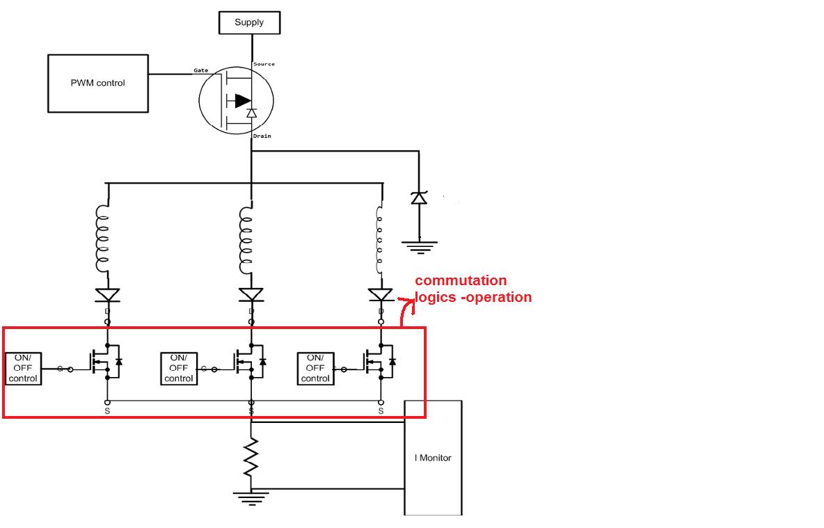
Pls find the BD of unipolar configuration,where top MOSFET is used for acceleration control and lower 3-MOSFETs are used for commutation based on Hall sensor feedback,
I think you should look at the DRV8343-Q1 device and use the independent FET mode. this will give you VDS protection on all of your FETs. You are also going to need an MCU to take your hall sensor inputs and commutate the motor driver.
Also on your schematic that you are showing the inductors do not have recirculation paths meaning that you are going to blow up your FETs. I would suggest you put diodes in parallel to the inductors that is pointing up to fix this.