This thread has been locked.

If you have a related question, please click the "Ask a related question" button in the top right corner. The newly created question will be automatically linked to this question.

DRV8305: Question for DRV8305

Part Number: DRV8305

Hi Team,

Customer designed the standard circuit of DRV8305 according to TI design. He confimed that there is no problem with the circuit. When configuring the DRV8305, the waveform is inconsistent when using the 6pwm output and the 3pwm output.

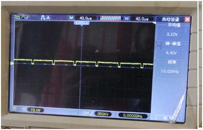
The figure below shows the output of the GHA of the DRV8305 being correct at 3PWM.

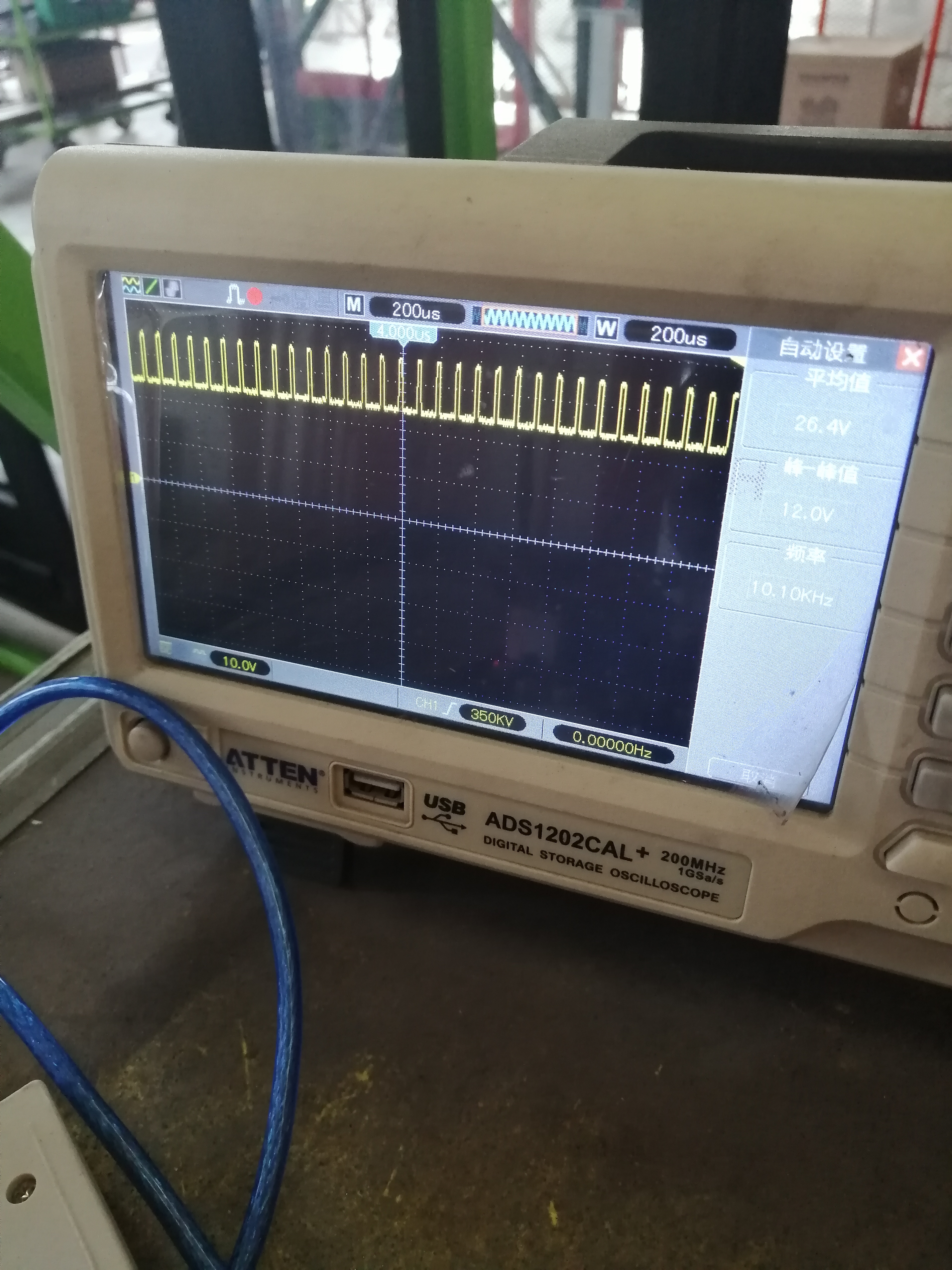
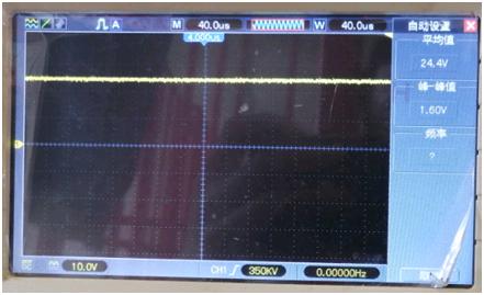
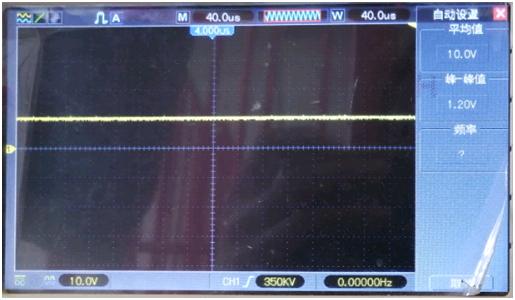
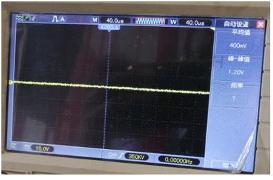
At 6PWM, The signal is biased by 24V. This will cause the MOS output to always be 24 v, although it fluctuates on the oscilloscope.

  • Annie,

    Thanks for posting on the Motor Drives Forum!

    Could you please post both scope images again but include the PWM inputs in the same plot?

    For the 3PWM case, please show us the three INHx signals and one of the OUTx signals.

    For the 6PWM case, please show us at least INHx, INLx, and OUTx for the same phase.

    Regards,

    -Adam

  • Hi Adam,

    Here is update from customer.

    Because the oscilloscope has one pen left, it can only be represented by a single signal. But the signals are collected in one mode.

    Output signal and input signal comparison chart in 6PWM mode.

    INHA is low

    INLA is low

    INHB is low

    INLB is 3.3V high

    INHC is 10kHz 3.3V, accounting for 10%

    INLC is low

    According to the above input signal, the current of the BLDC motor should go in from phase C and out of phase B. However, after the DRV8305 pre-drive, there was a problem with the signal. The GHA of phase A also goes high, causing current to go in phase A and phase C, but out of phase B. This is different from the customer's design.

    The signal input to MOS is expected to be as follows:

    GHA is 24V high (should be low)

    GLA is 0V low

    GHB is 0V low

    GLB is 10V high

    The GHC is a pulse signal that is biased by 24V, and the duty cycle of the signal is correct. (The output of the MOS becomes always high after being biased, and the PWM wave cannot be output)

    GLC is 0V low

    Customer would like to know:

    1. When the signals of INHx and INLx are both low, after pre-drive, it will become that GHX is high and GLX is low.

    2. When INHx is a PWM pulse, the GHX pre-driver will automatically bias 24V, and then add a 10V pulse waveform. This causes the MOS tube waveform to be incorrect.

    Thanks.

  • Annie,

    I think it would be best for the customer to try using an EVM, is this possible?

    Can you share the schematic?

    Regards,

    -Adam