Because of the holidays, TI E2E™ design support forum responses will be delayed from Dec. 25 through Jan. 2. Thank you for your patience.

This thread has been locked.

If you have a related question, please click the "Ask a related question" button in the top right corner. The newly created question will be automatically linked to this question.

DRV8872: VM pin burned-out

Part Number: DRV8872
Other Parts Discussed in Thread: INA301, DRV8876

In my application I use an INA301A1 in transparent mode to limit motor current to about 2A in case of rotor lock, as the DRV8872 OVC limit has a too much large tollerance (3.7 to 6.4A).
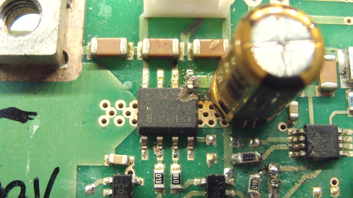
In a couple of cases I had the failure you can see in the attached photo: VM pin burned-out.
Power supply is 24 to 29V, ambient temp. 20..25°C, motor is simply turned on by 700..800 msec CW or CCW static signal every 2..5 seconds, no PWM used. What could be the reason for this kind of failure ?
Thank you in advance for your kind attention.
M.R.

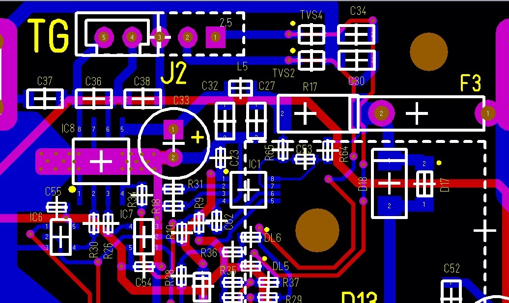
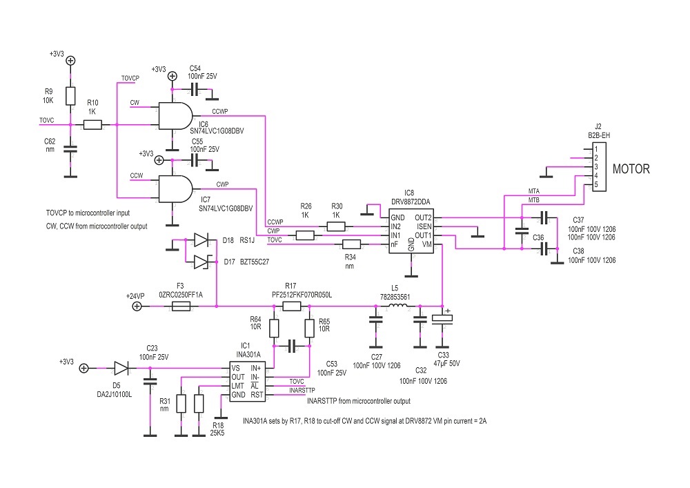
Here are also my pcb lay-out and electric diagram.

  • Hi Marco,

    I will study your issue and get back to you.

  • Hi, thank you Hector.

    In the meantime I provide to you further details.

    I removed from the circuit the IC1 (INA301) so the AND gates IC6, IC7 are still passing CW or CCW commands,

    then I programmed the microcontroller to generate an 800msec CW pulse every about 2.5 seconds.

    This is a record of IC8 (DRV8872) pin voltages with motor in free running without any mechanical load:

    - yellow = IN2    - blue = OUT2   - pink = VM   - green = direct voltage across R17 (50 milliohm)

    and this is the same but with the motor rotor locked:

    motor current is about 150mV / 0.05 ohm = 3A

    I soldered also a thermocouple to pin VM, in order to measure its temperature by a DMM.

    In the first case (rotor free) the VM pin remains at the room temp. (23°C)

    while in the second case (rotor locked) the pin temp. rises above 70°C in five or six ON-OFF cycles

    and seems to increase further and faster if I don't shut-off.

  • The DRV8872s I'm using are marked 8872 TI 84A P2DSG4 (last two characters with underscore).

  • Hi Marco,

    Apologies for the delay. I am targeting to give you a response in the next business day.

  • Hi Marco,

    We have reviewed your design and we have input:

    1. OCP vs Current Regulation:I see that you want to limit the motor current while the rotor stalls. What you indicated for OVC range of 3.7 to 6.4A is the OCP, which is there to protect the device and disable the outputs. Current regulation though, which is what you are trying to achieve with the INA301A IC, can actually be done at the 2 A current you are trying to regulate at. We believe the VM burn is caused by multiple problems that can be fixed by using the device's current regulation.
    2. The 100nF capacitors C37 and C38 are very large and can lead to very large currents when the outputs are energized. If possible, please consider smaller caps in the 10nF range.

    Current regulation section of datasheet:

  • Thank you Hector for your suggestions.

    About the current regulation feature, I didn't choose to use it because I would like to know when the rotor stalls but there is no feedback from the chip when the output current rises above the Itrip limit sets by the external Risen.

    If I'm not wrong, the nFAULT output changes only in case of OCP, TSD and UVLO and the OCP threshold is not adjustable.

    This is the reason I decided to use the INA to measure the stall current.

    About the 100nF EMI capacitors I removed them at all, but the game remains the same: temperature on pin VM rises quickly as in the case shown above.

    My feeling is that the rotor stall current is not enough to trigger the OCP (a short circuit on output will do that for sure) or heat up the silicon die to TSD (the chip is really well dissipated by the thermal pad) but is enough to melt, not immediately, just after some minutes, the bonding on the VM pin if not turned off in time.

    Now I put again the INA in its place, keeping it in transparent mode and set its ALn output to trip at about 2A.

    This is a record from the oscilloscope with the rotor stalled (yellow = DRV IN2, blue = DRV OUT2, pink = DRV VM, green = INA OUT equiv. to 1A/div)

    As the current rises above the INA threshold its ALn output chops the DRV IN2 input at about 67KHz, see the same picture with faster time base

    The average current is still high enough to heat up again the VM pin: this is the original situation that probably burned the DRV VM pin in the prototypes during long period tests.

    Now I found a way to avoid this issue: place a 100nF capacitor on C62 position and change R9 from 10K to 100K (please refers to the above diagram).

    This introduces a delay in the INA ALn output recovery time that slows down the chopping at the DRV IN2 input to about 1.9KHz, giving a lower average stall current that keeps the VM temperature stable, just about 10°C above the ambient temp.

    I hope this should solve my concern about the DRV failure.

    Of course there should be also other ways: use the INA in latch mode to turn off the DRV definitevely in case of stall, but in my case I have some other large motors (900 watts total) on the same power supply bus that produce various spikes that sometime trig the INA latch causing a false stop of the DRV.

    Or I should use the microcontroller to cut the CW/CCW signal when the INA trips, but in this case the reliability of the system will depend by the software and this is not the case, as the software itself for some reason could stall losing the control.

    Just one last question: could the DRV8872 Q1 automotive version be much more robust against this kind of failures ?

  • Hi Marco,

    Clarification:

    1. Removing the capacitors or, at least lowering their values, can help in reducing the current transients when the OUTx turn ON from not being energized.

    Feedback:

    1. I see you have bulk cap C33 and a PI filter with a 100nF capacitor C32, yet I do not see decoupling capacitor that should be between the VM pin and C33 (placed as closed to the VM and GND pins of the device as possible). If you meant C32 to be the decoupling capacitor, please place it as close to VM/GND pins as possible.
    2. I do not see a very good GND pour for current handling and energy movement across the PCB. Making sure you can visualize the flow of current through your layour and that there a good return path to the bulk cap/supply and down to ground can lower resistance/parasitics in the design. Also, make sure the OUTx and VM based traces are 20 mils for any current handling necessity.
    3. The -Q1 version is qualified for automotive applications and for your issue I do not see a benefit for making the change.
    4. The soldering seems hand done and what worries me is that, given the VM blow up we are seeing, a contributing factor can be the soldering of the Thermal Pad. If you can, please verify your PAD soldering follows the guidelines of the PowerPad Made Easy App Debrief http://www.ti.com/lit/an/slma004b/slma004b.pdf
    5. I still push for either taking the DRV8872, utilizing an external circuit to find out when current regulation kicks in or, what I suggest is the best solution to your design, is to move towards the DRV8876. The benefit of the change to DRV8876 are that it has nFAULT notification when current chopping kicks. Please see the datasheet http://www.ti.com/lit/ds/symlink/drv8876.pdf and the sections 7.3.3.x for current regulation:

  • Hi Hector,

    thank you for your futher suggestion.

    Here are my comments about them:

    1) I've added a ceramic 100nF 50V by-pass cap. very close to the DRV pin VM (in the narrow space between the IC and the bulk cap.) but it doesn't change the situation. Anyway, in the pcb revision I'll add it.

    2) my layout is not so different from the layout in fig.15 of the SLVSCZ0C DRV8872 data sheet. VM trace width is 40 mils, OUT traces 20 mils only for a while, then became 30 mils.

    3) Ok, I will not consider the Q1

    4) soldering of the components have been made by SMT stencil and SMT owen. Only the INA set resistors visible on the right down corner of the picture have been soldered by hand.

    5) I will not use the DRV8876 for these reasons:

    a) the cycle-by-cycle features requires a continuous controlling scheme by the microcontroller and in my case the system reliability can not depend by the software reliability. The software have to know when the rotor stalls but the circuit have to be intrinsically safe even if the software fails

    b) the fixed-off-time mode should be OK, but in this case the nFAULT response is only in case of overcurrent only, exactly as it is with the 8872, so no any chance in this mode to have a rotor stall feedback

    c) electrical characteristics of 8876 are lower than the 8872 (37V VMmax oper. vs 45V VMmax oper., 40V VMmax abs. vs 50V VMmax abs, 350 typ./420 max mOhm RdsON vs. 307 typ./360 max). I prefer to have an higher VM max due to the presence of spikes on the power supply bus, as I already wrote.

    I added to my circuit the Risen on the DRV pin Isen. With 0.2 ohm it goes now in current regulation mode and the VM average current rises slowly the VM pin temperature at about 10°C above amb.temp. after several minutes.

    So I decided to solve the trouble in this way: keep the 8872 adding the Risen resistor to decrease the average current and the VM pin temperature and also keep the INA to detect the rotor stall.

    If you don't have no any more topic to suggest, I'm ready to close the thread.

    Thank you,

    Marco

  • Hi Marco,

    Thank you for the discussion and the trials conducted on your end. If you application is achieving it's end goal, that is good to hear. I have the following input if you wish to keep the INA and improve the current measurement design:

    1. The R17 resistor should be placed after the bulk cap C33 and before the new bypass cap you added. Reason for this suggestion: You need to measure the load current, and the bulk capacitor provides instantenous current for those slewing moments during driving. You are currently measuring the current pulled from the PSU, but you need to measure the current pulled from the PSU + Bulk cap. This change will give you an accurate measure of current for your system.

    If you deem the thread can be closed, please do so. Again, thank you.