This thread has been locked.

If you have a related question, please click the "Ask a related question" button in the top right corner. The newly created question will be automatically linked to this question.

DRV8860: Fault Register read waveform error?

Part Number: DRV8860

Hi,

I am writing an embedded driver for the DRV8860, and the fault register read command doesn't seem to behave as the datasheet specifies.

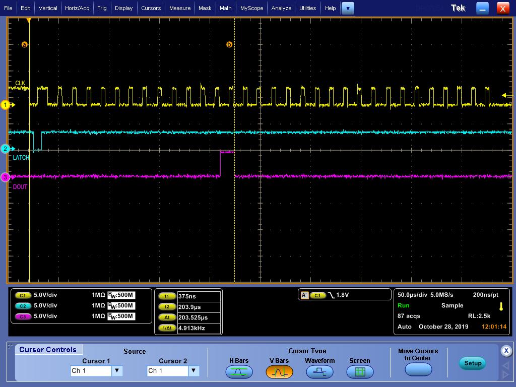
The datasheet's waveform for reading the fault register shows that the clock must be pulsed before the MSB of the fault register can be read on DOUT. However, when I do this, the data I read back is shifted left by a clock cycle and bit. The MSB of the fault register appears to show up on DOUT as soon as LATCH is brought high, and disappears after the first clock pulse.

In addition, the read fault register waveform in the datasheet seems inconsistent with the read data and read control register waveforms. For both of those waveforms, the MSB is correctly shown to appear on DOUT when LATCH is brought high.

  • Hi Robert,

    We will have to investigate this, and it may take until the end of the week.

    While waiting, can you provide a scope capture of the read of the fault register? It would be ideal if you have the outputs configured with several open loads to make reading the data easier.

  • Hi Robert,

    Please see the attached scope capture from the DRV8860EVM. An open load fault was created on OUT3 to allow show the full 16 bits of data.

    In addition to the image, the DRV8860EVM firmware can be found in the Design files (Hardware: DRV8860EVM) at 

    The firmware be used to determine how the MSP430 on the DRV8860EVM is controlling the device.

    Please provide a scope capture of your transaction or match the sequence shown.  

  • Hi,

    Sorry about the late reply, my work's email filter blocked the forum notifications.

    I've reproduced the CLK/LATCH waveform you have provided, with an open load fault on OUT3.

    I have found that this waveform can produce two distinct results. The first time I read the state after nFAULT is brought low (or perhaps when it changes), I receive the fault register shifted by one bit:

    When I read the fault register again any time after that, I receive what seems to be the same waveform you provided:

    If I read back the fault register as I described previously, it appears to return the correct value with every time:

    Below are the same three waveforms with an OCP fault on OUT8 instead of an OL fault on OUT3 to illustrate the behavior of the MSB of the fault register:

    Note that I've drastically slowed down CLK for these waveforms to illustrate that it isn't a timing issue. I get these same results at my intended CLK of ~50KHz.

  • Hi Robert,

    No worries about the delay.

    Do you have a further question?

  • Can you see the images I posted in the previous post? They aren't showing up for me.

    Mostly I'm trying to determine which fault reading waveform is correct, since the one in the datasheet is slightly different than the one provided in the sample code, which is different than the one I found to work. I'd prefer some clear answer on this to provide the FPGA engineer on how to update his driver.

  • Hi Robert,

    The images are not visible to me either.

    Can you try sending the images attached in a zip file? Please place a _1 through _6 at the end of the images to designate the position in the original response.

    If nothing is obvious, we will have to do some additional investigation.

    The next response will probably be Tuesday next week as I am unavailable for a few days.

  • Hopefully this works:

    DRV8860_captures.zip

    Edit: the nFAULT states here are triggered by me enabling/disabling a faulted channel using the data register write command.

  • Hi Robert,

    Yes the images are now visible. Thank you.

  • Hi Robert,

    I was not able to get back into the lab to confirm the waveforms. I hope to have a response by 10/23, but will not know for sure until tomorrow.

  • Hi Robert,

    Sorry for the delay. I have still not been able to get back to the lab. 10/28 is the new target to attempt lab work.

    While waiting I looked at the EVM code. There appears to be a special sequence that attempts to "clear the false pushing of fault register".

    Once the pattern is written the fault register is read.

    See below:

    case 0xa6: // read back fault register
    //LATCH-CLK pattern to clear the false pushing of fault register
    CLK_HIGH;
    LATCH_HIGH;
    Delay_us();
    CLK_LOW;
    Delay_us();
    LATCH_LOW;
    Delay_us();
    CLK_HIGH;
    Delay_us();
    LATCH_HIGH;


    for(ir=1;ir<=8;ir++)
    {
    CLK_HIGH;
    Delay_us();
    CLK_LOW;
    Delay_us();
    (P3IN & BIT2)?( ReadBack_Fault[0] |= (1<<(8-ir)) ):( ReadBack_Fault[0] &= ~(1<<(8-ir)) );

    }

    for(ir=1;ir<=8;ir++)
    {
    CLK_HIGH;
    Delay_us();
    CLK_LOW;
    Delay_us();
    (P3IN & BIT2)?( ReadBack_Fault[1] |= (1<<(8-ir)) ):( ReadBack_Fault[1] &= ~(1<<(8-ir)) );

    }

    for(ir=1;ir<=8;ir++)
    {
    CLK_HIGH;
    Delay_us();
    CLK_LOW;
    Delay_us();
    (P3IN & BIT2)?( ReadBack_Fault[2] |= (1<<(8-ir)) ):( ReadBack_Fault[2] &= ~(1<<(8-ir)) );

    }

    for(ir=1;ir<=8;ir++)
    {
    CLK_HIGH;
    Delay_us();
    CLK_LOW;
    Delay_us();
    (P3IN & BIT2)?( ReadBack_Fault[3] |= (1<<(8-ir)) ):( ReadBack_Fault[3] &= ~(1<<(8-ir)) );

    }

    Delay_us();
    //LATCH_LOW;
    break;

    Best Regards,
    Rick Duncan
    Motor Applications

  • Hi,

    Yes, I did see that comment in the MSP430 firmware and it struck me as a bit odd. I've implemented that pattern as stated in the MSP430 source which can be seen in images 1, 2, 4, and 5 of my zip file.

    It's a different waveform than the one specified in the datasheet, but I can say that both the waveform from the datasheet and the one produced by the MSP430 sample code produce erroneously shifted results.

    The commented out LATCH_LOW at the bottom of the case statement in the MSP430 code there is also interesting.

  • Hi Robert,

    I was able to determine the difference in EVM code between the first read and any subsequent reads. The first read has CLK high before entering the Read routine while any subsequent reads has CLK low.

    When the CLK is high, there is no rising edge to shift the data as needed. First read is shown below.

    Subsequent reads are shown below:

    It appears the routine should set CLK low prior to entering the read routine. Then the first rising edge generated in the routine will shift the data as described in the code.

  • Hi,

    In the waveform generated by my port of the EVM code (as seen in images 1 and 2 of my previous zip file), my clock already remains and starts at idle LOW, so it's LOW when initiating a read command, as in your second image above. In addition, data seems to be shifted out on a falling edge, such that it's read on a rising edge by the microcontroller.

    Assuming this "LATCH-CLK pattern" from the EVM sample code is correct, I can reproduce the shifted bit far after the initial read of the fault register when booting the microcontroller, as seen in image 1 of my previous zip file. Specifically the data I receive is shifted by one bit for every first read after nFAULT changes from HIGH to LOW. Every subsequent read of nFAULT (see image 2) after that using that pattern returns the data correctly, until nFAULT toggles again.

    The "false pushing of the fault register" as mentioned in the EVM code may be what I'm seeing on DOUT immediately when nFAULT toggles (see image 4), but the pattern provided seems insufficient to clear it.

  • Hi Robert,

    Sorry for the delayed response. I did not see a question in your last response. Do you still need some assistance?

    The data is shifted out on a falling edge. In the code snippet, the data is read after the falling edge and just prior to the rising edge of the clock.

    From my interpretation of the code and observation on the bench, this one clock shift appears to be required for each read of the fault register to obtain the correct data from the fault register.

  • In your previous post, by "first" read do you mean the first read after booting the firmware, and "subsequent" as in every read after that?

    Because what I'm seeing is the first read after every time nFAULT toggles is shifted by one bit, as opposed to just the absolute first read after powerup, and that the starting state of the clock has nothing to do with whether the data I'm reading back is shifted or not (as seen in the first image of my previous zip file).

    Basically what I'm asking is:

    The provided clock-latch pattern appears inadequate to reset the fault register state whenever nFAULT toggles. However, data is read correctly with this pattern on subsequent reads. Is there a pattern that actually clears/resets the fault register state that doesn't involve reading the whole thing?

    As it stands, my current solution is to read the fault register twice when I detect nFAULT has toggled, although I have concerns about what happens when nFAULT toggles while I'm reading it twice.

    It would also be useful to have this fault register behavior documented as datasheet errata as opposed to a comment in the sample firmware.