This thread has been locked.

If you have a related question, please click the "Ask a related question" button in the top right corner. The newly created question will be automatically linked to this question.

CCS/DRV8323R: nFAULT always on.

Part Number: DRV8323R
Other Parts Discussed in Thread: MOTORWARE

Tool/software: Code Composer Studio

Hi guys,

I've a strange problem with a custom board.

I'm using DRV8323RH and a F28069M. I made a simple brushless sensorless torque control.

You can see the "power drive" schematic attached to this post.


I've control all over the pins and I don't see strange behaviors. So, I'm trying to use a modded version of "motorware lab5a".

When I set "gMotorVars.Flag_enableSys" flag always it's ok.

When I set "gMotorVars.Flag_Run_Identify" flag nFAULT goes on and the driver latch to error condition. I try to reset with a pulse on ENABLE pin but the nFAULT condition immediately reappears.

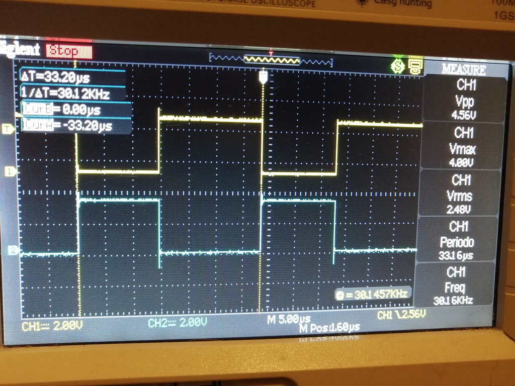
In this condition if I control the MCU with the Oscilloscope I can see the PWM signals over all "MOS gate" signals.

Someone can help me debug this issue?

Regards,


P.S.:

- Internal Buck regulator: NOT USED;

- Voltage +VB : +48Vdc;

- MODE Pin: set to GND (6x PWM);

- VDS control: disable...VDS tied to VDD (at the moment...);

  • Stefano,

    Thanks for posting on the motor drives forum!

    Can you confirm the IDRIVE setting you are using?

    The schematic shows 60/120mA setting and FETs with 20nC of Qgd.

    If you remove power from the system for several seconds and then reapply the power, does the fault clear?

    Regards,

    -Adam

  • Hi Adam,

    yes, this is the setting mounted in the PCB.

    Now, I'm trying this steps:

    1) Flag_enableSys -> 1 (nFAULT not set)

    2) Flag_Run_Identify -> 1 (nFAULT turn on). If I try to reset it with a pulse on ENABLE pin, nFAULT blink for an instant an then it set again.

    3) Flag_Run_Identify -> 0 (nFAULT is still on). If I try to reset it with a pulse on ENABLE pin, nFAULT turn off but if I try to re-run the motor (Flag_Run_Identify -> 1) it always turn on.

    If I remove power from the system for several seconds and then reapply, nFAULT not turn on but I'm not be able to run the motor.

    Regards,

  • Stefano,

    When the fault light is on, please check the following nearest the DRV device:

    1. VM voltage.
    2. VCP voltage.
    3. Check if nFAULT is constantly LOW or is it toggling?
    4. Is the DRV hot?

    When Flag_Run_Identify -> 1 if you check the gate-to-source voltage of all HS and LS FETs, do you see the FETs switching? Are there any abnormalities in the gate waveforms?

    Regards,

    -Adam

  • Hi Adam,

    regarding your questions, during FAULT condition:

    1. VM is +48.40V (from lab power supply);

    2. VCP measure +61.20V with 1.20V ripple;

    3. nFAULT is costantly low;

    4. No, DRV seems to be more or less 25°C; (Yesterday I changed component with a new one);

    5. "Vgs" are ALL zero.

    I can't understand. Yesterday night with low noise lab, when I've checked VCP with oscilloscope. Touching the C21 capacitor side I heared a noise (PWM charge pump?!). This noise disappeared when I removed the probe (I try sometimes). This is the only thing I suppose not normal.

    PS: ENABLE is +3v3 and CAL is tied to GND.


    Regards,

  • Stefano,

    Are you driving the inputs of the DRV when the fault occurs?

    Do you have all FETs installed?

    Regards,

    -Adam

  • Hi Adam,

    no, the FAULT occour when I start PWM signals on the inputs.

    If I stop PWM and then I reset DRV, FAULT go away ... just turn ON PWMs and fault lights up again

    I controlled all PWM input and I not saw strange things.

    All MOSFET is installed and seems to be fine.

    Regards,

  • Stefano,

    Can you explain your statement: "I controlled all PWM input and I not saw strange things".

    Regards,

    -Adam

  • Hi Adam,

    sorry for my bad english.

    I try to explain my statement.

    Whit only "Flag_enableSys" set the PWM signals are not generated from MCU. When I set also "Flag_Run_Identify" MCU start to generate PWMs signals on pwm1a, pwm1b, pwm2a, pwm2b, pwm3a and pwm3c. At the same time DRV set FAULT pin...but PWM signal coming from MCU are still present in DRV inputs (INHA, INLA, INHB, INLB, INHC, INLC). I checked with oscilloscope these signals (see the pic attached: PHASE A, INHA, INLA). The switching freq is set to 30KHz.

    Can be an hardware issue? I don't use buck regulator and I've not connected these pins (see the schematic upward).

    Regards,

  • Hi Adam,

    I noticed a problem in MOS component library (GATE pinout).

    I downloaded this from "mouser" website but I think it may be wrong.

    Please can you check my schematic and the datasheet:

    Can you confirm my thesis?! Gate pin seems to be in position 4 instead of 1.

    Regards,

  • Stefano,

    The pinout on the Vishay datasheet shows pin 1 as the gate, your schematic shows pin 4 as the gate, this would explain why you are seeing the fault as the gate signal is connected to your source connection at all times through the FET internally.

    You can confirm this by removing all your FETs and retrying your experiment.

    Regards,

    -Adam