This thread has been locked.

If you have a related question, please click the "Ask a related question" button in the top right corner. The newly created question will be automatically linked to this question.

DRV8844: driver operates slower in one direction than other

Part Number: DRV8844

Hi,

I'm using the DRV8844 to drive a single DC brushed motor, so I'm connecting the outputs in parallel to increase the available current (as discussed here). I have OUT1/2 shorted and OUT3/4 shorted, and same for IN1/2, EN1/2, and IN3/4, EN3/4.

I'm using slow decay drive, so PWM'ing the INx pins and keeping ENx constant logic high (as shown in Table 3 of the datasheet).

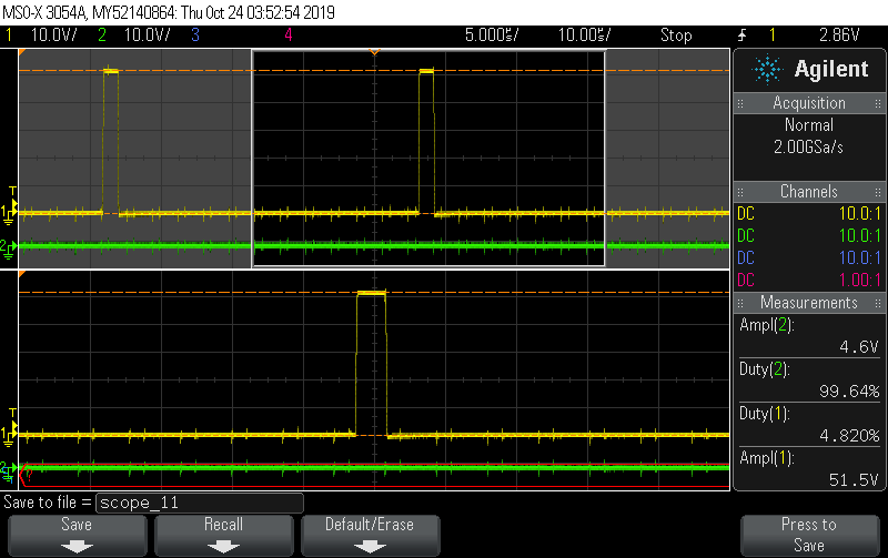
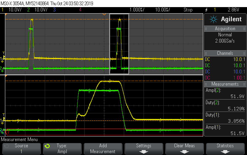
It is working; however, I noticed that the speed is pretty significantly different depending on which INx pair I drive with the PWM. The direction of the IN3/4 pair's max speed is about 20% that of the IN1/2 pair. I confirmed that this is independent of the motor, as I reversed the motor leads and the slower direction stayed with the same pair. I've also confirmed that the PWM signals are as expected; they're exactly the same for each pair.

I'm at a loss as to why I should be seeing such a discrepancy?

thanks,

Ryan

  • Hi Ryan,

    There is no reason for this discrepancy. Can you provide scope captures of the output voltages in both directions?

    This should provide some additional clues.

    Also, how did you connect the SRC12 and SRC34 pins?

  • Hi Rick,

    Probing the output pins does seem quite revealing. When moving forward (the direction that works), I get PWM on the active channel and nothing on the inactive one, but when moving in reverse I actually get PWM on both channels. See following scope captures, taken at 5% duty cycle pwm (I'm running at 22kHz):

    FORWARD MOVE:

    REVERSE MOVE:

    Here's my schematic for reference:

    Thanks for your support,

    Ryan

  • Hi Ryan,

    Thanks for the information.

    The SRC12 should be connected to SRC34 in your schematic. Please refer to section 7.2 (Functional Block Diagram).

    Without this connection, there is no path for the current to flow through the low side FETS in OUT1/OUT2.

    Once this connection is made you should see the desired operation.

    Also, what is the -V_IN  voltage? I see no problem but want to make sure the voltage difference between VM and -V_IN does not exceed the recommended 60V.

  • That fixed it, thanks Rick

    The difference between VM and -V_IN is 48V.

    I actually ended up tying the two grounds together because I was seeing a big difference between the logic ground and -V_IN, and I had two chip failures which I suspect was due to that.