This thread has been locked.

If you have a related question, please click the "Ask a related question" button in the top right corner. The newly created question will be automatically linked to this question.

MOSFET In Constant Current mode

Other Parts Discussed in Thread: CSD19536KTT, CSD19536KCS, CSD19506KCS

HI,

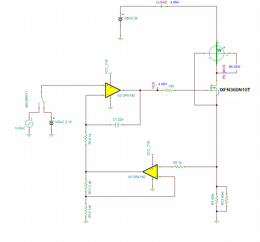
I Have designed an Electronic load. (Please find the circuit below). I-load = VDAC / (R3 || R13). The mosfet is rated for 100V and 360A. when my VBUS is 24V and my current is exceeding 7A, My MOSFET is getting damaged. What is the reason for this to happen? am I Missing any parameter to consider?

Note: Mosfet is mounted on a very big heat sink and Up to 7A it is working fine.

Regards

Vishal Kakade

  • HI Vishal,

    Thanks for the inquiry. I'm thinking the failures are because the FET is either getting too hot or you're violating safe operating area (SOA). I reviewed the IXFN360N10T datasheet including maximum power dissipation and safe operating area (SOA) for this device. The datasheet specifies 830W maximum power dissipation at a case temperature of 25degC. This is a calculated value based on maximum junction temperature (175degC), case temperature (25degC) and junction-to-case thermal impedance (0.18degC/W). This is detailed in the blog below. This power dissipation needs to be derated if the case temperature is different from 25degC. For example, at Tcase = 100degC, the maximum power dissipation is as follows:

    Pmax = (Tjmax-Tcase)/RthetaJC = (175degC - 100degC)/0.18degC/W = 93.75W.

    In your application, the FET is operating in the saturation region and has IDS = 7A and VDS ~ 24V giving a power dissipation of 168W. Working this backwards, the temperature rise from the case = 168W x 0.18W/degC = 30degC and the maximum case temperature for Tj = 175degC = 175degC - 30.2degC = 145degC. Keep in mind, that you typically want some derating below Tjmax for reliability purposes. Let's assume 25degC derating so the maximum case temperature is now 125degC. I would recommend measuring the case temperature as you increase the load current to see how hot the device is getting.

    The other consideration is SOA for the FET. Please check the second blog below for more information on how TI tests and rates SOA for our FETs. TI tests to failure and derates SOA to insure our FETs will operate reliably within the SOA curves provided in the datasheet. Not all vendors test in the same manner or derate their parts.

    The SOA curve in the IXFN360N10T datasheet is provided at Tc = 25degC. Again, you need to derate this curve when the case temperature is not 25degC. From the SOA curve in the datasheet I estimate the maximum DC SOA current at VDS = 24V is about 15A. You can linearly derate this as follows: (Tjmax - Tcase)/(Tjmax - 25) x Isoa. For example, if the case temperature is 100degC, then the SOA current = 15A x (175degC - 100degC)/(175degC - 25degC) = 7.5A. Again, I recommend measuring the case temperature. Please let me know if you need any further assistance.

    Welcome back, fellow FET enthusiasts to part three of the " Understanding MOSFET Data Sheets " blog series! Today I’ll be talking about MOSFET current ratings and how they’re not real. Ok, so maybe a better…
    By in Technical articles > Power management

    Other Parts Discussed in Post: CSD19536KTT Welcome back, fellow FET enthusiasts to part two of the " Understanding MOSFET Data Sheets " blog series! As a product marketing engineer for power MOSFETs ,…
    By in Technical articles > Power management

  • Hi John,

    Thank you for the detailed explanation. As per your suggestions, I see that the only reason for the failure is heat generation. But I Have a few more questions.

    I Was increasing the current in steps of 1A / Sec. And it failed from a transition from 7 to 8A. 

    Is this failure has anything to do with VDS and ID?

    If I use a Higher VDS rated mosfet, will it work?

    Or its purely a thermal failure? because I hardly Turned it on for 7 or 8Sec.

    My heat sink is also very big. Do I need a faster cooling mechanism for this to work? Because the MOSFET is rated for more than 800W.

    I am thinking to replace the MOSFET with "IXFN60N80P"


    Regards

    Vishal Kakade

  • Hi Vishal,

    To answer your questions, I do not believe that you are exceeding the breakdown voltage, BVDSS, of the FET with a 24V source in this application. This is not a switch-mode where you are turning the device on and off as fast as possible. Under those conditions, parasitics may cause unwanted VDS spikes that exceed the absolute maximum and cause the FET to avalanche which can be destructive. That being said, I don't think a higher voltage FET is going to help. I believe the failure totally has to do with VDS x ID or power. For the heat sink to be most effective, you need to ensure that the interface between the case and heat sink is low thermal impedance. Thermal grease or a thermal pad should be used and fasteners tightened to the proper torque. Because you are heat sinking the FET, my guess would be the failures are due to SOA which can start as a hot spot on the FET die and lead to thermal runaway. Paralleling FETs is an option to spread the current and heat over two devices and a larger surface area. You need to use a separate gate resistor for each device and try to keep the power paths symmetric.

  • Hi Vishal,

    After speaking with a colleague, I had a few more comments. First, I'd recommend reaching out to the MOSFET vendor to get their inputs and send a failed device to them for failure analysis. And second, TI also makes power MOSFETs although not in the same package. A FET or FETs in a TO220 package can also be attached to a heatsink. Something like the CSD19506KCS (80V) or CSD19536KCS (100V).

  • Hi John,

    I tried STE26NA90 & IXTN36N50  With these MOSFETs, my design is working perfectly fine. I tested it till 11A. Even though these MOSFETs are rated for up to 400W, I am able to dissipate 280W easily.

    But with this, My rise time is lowered. There is a requirement for current to go from 0 to 3A within 10uS Which was achievable with the previous MOSFET but it was failing after 7A. With these new MOSFETs, I am going to 11A. But my rise time is around 20uS.

    I wanna know, What is going wrong? These MOSFETs are rated for half the power compared to the MOSFET I was using before and Even the max temp is less for new MOSFETS.

    Regards

    Vishal kakade.

  • Hi Vishal,

    I do not know the answer to what is going wrong in your application. The FETs are not TI products and I'm afraid I am not very familiar with them. As I stated previously, my best educated guess is that the failures are related to the SOA of the device. I looked at the datasheets for the devices that you say are not failing and it appears that the SOA is better for both compared to the original FET. However, I don't believe I can provide you with any useful support beyond what we have discussed already. I highly recommend you contact the FET vendors to discuss your application in more detail.

  • Hi John,

    Thank you for your support.

    Regards

    Vishal