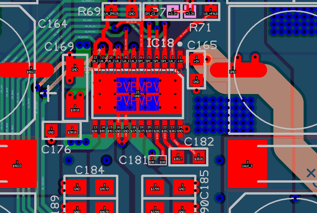
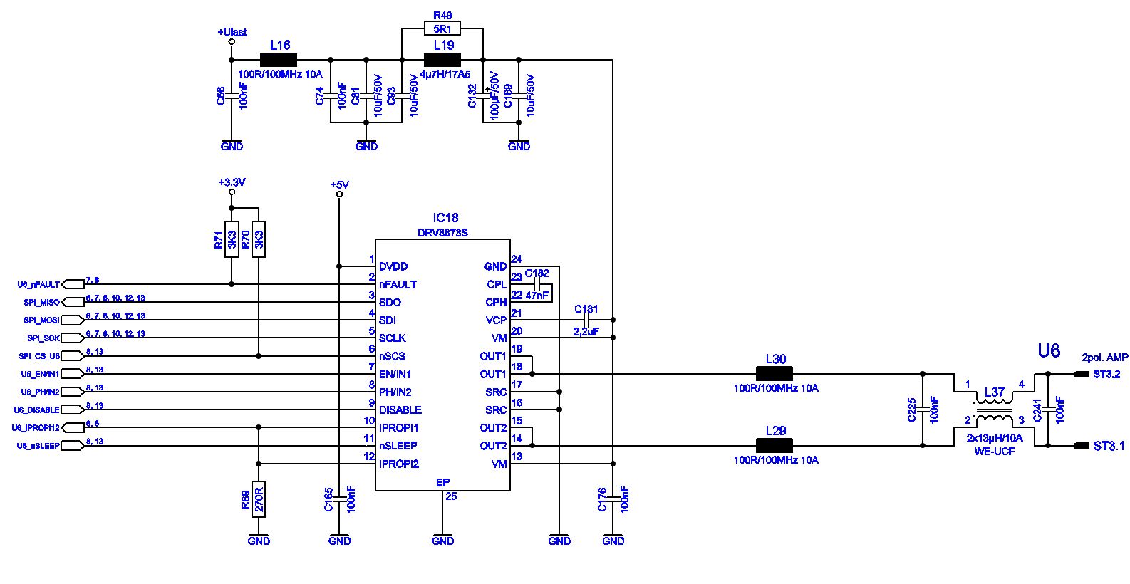
We have connected the motor driver as shown in the wiring diagram. The supply voltage for the H-bridge is between 24 and 34V. A DC motor with brushes is connected.
The motor needs a current of up to 750mA during operation.
The IC1 Control register is configured: loc_data := %0101 0000; //TOFF 40 µS, Output INx, 10.8V/µs risetime, PH/EN PWM.
The PWM has a frequency of approx. 20kHz with which the motor is controlled.
We now have the problem that one or both Low Side Fets have a short circuit after the operation of the motor and so the motor driver is defective. At the moment we can't explain where the error is.
The heat dissipation is relatively well possible over the circuit board. We use a 2mm PCB with 70µ outer copper.
The GND vias are connected on the top, GND and bottom layer to get the heat out of the IC. We operated the circuit on the laboratory table at approx. 20°C. In the finished device there is a heat conducting foil underneath the circuit board and an aluminium plate connects the circuit board with the housing.
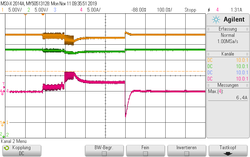
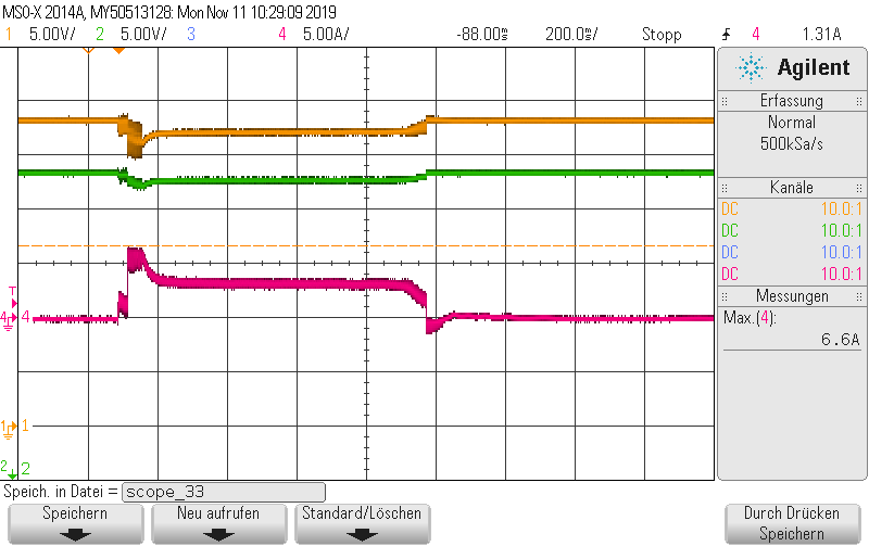
The picture shows the AC voltage at PIN 13 of the IC when switching on and off the motor.
I would be pleased if you could help us there. The strange thing is that we have used the circuit on our prototypes and had no problems with it until now.