This thread has been locked.

If you have a related question, please click the "Ask a related question" button in the top right corner. The newly created question will be automatically linked to this question.

Motor Parameter Measurement with Motorware v1.01.00.18 on TSM320F28069

Other Parts Discussed in Thread: DRV8305-Q1EVM

Hello,

I am having an issue getting the motor parameter measurment feature of InstaSpin-FOC to work properly with our custom hardware. We are using the TSM320F28069M to implement Field Oriented Control of a motor. I have worked through the previous labs (1b and 1c) and verified that the current and voltage feedbacks are working correctly. We have received most of the necessary motor parameters from the manufacturer but I still need USER_MOTOR_RATED_FLUX before I can attempt to implement the torque controller in lab 4.

Attempting to perform motor parameter measurement has repeatedly resulted in the controller creating an overcurrent event similar to the one shown below. The event occurs either at the very end of EST_State_RoverL or at the very beginning of EST_State_Rs. The image below shows the three low side gates at the event (yellow- phase C, blue- phase B, pink- phase A, green- bus current):

The next image shows the current feedback for each phase at the event (yellow- phase C current, blue- phase B current, pink- phase A current, green- bus current). The current feedbacks have an offset of 1.65V and are measured across low side shunt resistors:

The overcurrent threshold in our hardware is 60A but based on the settings in user_j1.h the system shouldn't exceed 15A. These are the parameters I have set in that file:

#define USER_MOTOR_TYPE                                     MOTOR_Type_Pm  // Motor_Type_Pm (All Synchronous: BLDC, PMSM, SMPM, IPM) or Motor_Type_Induction (Asynchronous ACI)
#define USER_MOTOR_NUM_POLE_PAIRS              (2)            // PAIRS, not total poles. Used to calculate user RPM from rotor Hz only
#define USER_MOTOR_Rr                                           (NULL)         // Induction motors only, else NULL
#define USER_MOTOR_Rs                                          (NULL)        // Identified phase to neutral resistance in a Y equivalent circuit (Ohms, float)
#define USER_MOTOR_Ls_d                                       (NULL)     // For PM, Identified average stator inductance  (Henry, float)
#define USER_MOTOR_Ls_q                                       (NULL)     // For PM, Identified average stator inductance  (Henry, float)
#define USER_MOTOR_RATED_FLUX                        (NULL)        // Identified TOTAL flux linkage between the rotor and the stator (V/Hz)
#define USER_MOTOR_MAGNETIZING_CURRENT  (NULL)         // Induction motors only, else NULL
#define USER_MOTOR_RES_EST_CURRENT           (3.0)          // During Motor ID, maximum current (Amperes, float) used for Rs estimation, 10-20% rated current
#define USER_MOTOR_IND_EST_CURRENT            (-3.0)         // During Motor ID, maximum current (negative Amperes, float) used for Ls estimation, use just enough to enable rotation
#define USER_MOTOR_MAX_CURRENT                    (15.00)        // CRITICAL: Used during ID and run-time, sets a limit on the maximum current command output of the provided Speed PI Controller to the Iq controller
#define USER_MOTOR_IDENT_FREQUENCY_Hz     (20.0)
#define USER_MOTOR_FLUX_EST_FREQ_Hz           (9.3)          // During Motor ID, maximum commanded speed (Hz, float), ~10% rated

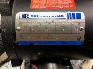
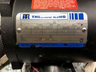
and the namplate for the motor:

Modifying the different current thresholds doesn't have any impact on the event and I've double checked that they are set correctly based on nameplate values for the motor. Since it looked like the issue was related to the R over L estimation procedure I have tried modifying the USER_R_OVER_L_EST_FREQ_Hz define to values between 100 and 300 at increments of 10 (the images above were captured when it was sent to 200). This has only had the impact of prolonging the overcurrent fault. Another thing that I've noticed is the shaft never rotates regardless of the settings I use. I've tried a second motor and achieve the same result. 

Any recommendations on troubleshooting this issue further or settings that are relevant and I may have overlooked would be greatly appreciated. 

  • Hi Alex,

    Your post has been assigned to an expert. While you wait for a response, please check out the following FAQ Page: https://e2e.ti.com/support/microcontrollers/c2000/f/171/p/855709/3164191#3164191

    Best Regards,

    Marlyn

  • You should set the identification parameters based on the specification of your motor, it seems like the USER_MOTOR_FLUX_EST_FREQ_Hz is not right you set.

    #define USER_MOTOR_RES_EST_CURRENT (1.0), 10-20%  of the rated current

    #define USER_MOTOR_IND_EST_CURRENT (-1.0), 10-20%  of the rated current

    #define USER_MOTOR_MAX_CURRENT (5.0)

    #define USER_MOTOR_FLUX_EST_FREQ_Hz, 10~20% of the rated frequency 

    If you still have problems, you may try to use the TI EVM kit to identify the motor first. The sensing current and voltage signal maybe not good on your board though you have run the lab01b and lab01c on the board.

  • Thank you for your quick response Yanming.

    The rated frequency of the motor I am using is 93Hz so my setting for USER_MOTOR_FLUX_EST_FREQ_Hz appears to be in the acceptable range. I have tried increasing it to 20% (18.6Hz) but that did not make a difference in operation. USER_MOTOR_RES_EST_CURRENT, USER_MOTOR_IND_EST_CURRENT, and USER_MOTOR_MAX_CURRENT are also correct based on the nameplate rated current of 15A.

    Yanming Luo said:
    If you still have problems, you may try to use the TI EVM kit to identify the motor first. The sensing current and voltage signal maybe not good on your board though you have run the lab01b and lab01c on the board.

    As I said in my original post, I have already gone through the process of verifying the voltage and current feedbacks on my custom hardware using labs 1b and 1c. The results I got for the voltage feedbacks in lab01b are shown below:

    The current feedbacks from lab01b:

    The results I got when graphing the angel output, reference Iq, and actual Iq in lab01c:

    Is there anything else I can do to verify the current and voltage feedbacks are working correctly?

    Do you have any other recommendations for settings to look at based on the nameplate values for the motor I am using?

    Are there any motor parameters other than the ones I have mentioned previously that have an impact on the motor parameter measurement?

  • Bumping this thread to hopefully get a response. 

    I used the DRV8305-Q1EVM to try to measure the motor parameters using lab02b. This was also unsuccessful. The only modifications I made were setting the appropriate motor parameters based on the nameplate values I posted previously. The fault LED on the board was triggered at the end of R over L estimation or the start of Rs estimation just like on our custom hardware. The motor never spun regardless of the estimation current settings or estimation frequency I tried. It seems like the issue is related to the FAST Estimator and not the motor parameters as those are all correct based on the "InstaSPIN-FOC™ and InstaSPIN-MOTION™ User's Guide." Using the eval hardware would seem to rule out any issues with the current or voltage feedback circuits. 

  • As replied to you above. If you make sure that the hardware kit is good or you are using the TI EVM kit, you just need to tune those variables in user.h based on your motor. Please ensure the motor type is right, and remove the load from the motor.

  • Can you make sure the motor is a PMSM? What's the rated frequency and pole pairs of the motor? Keep tuning these variables as mention above until the motor spin smoothly in each identification phase.

    We 'd like to close the thread first, please create a new one if you still have any other questions.