This thread has been locked.

If you have a related question, please click the "Ask a related question" button in the top right corner. The newly created question will be automatically linked to this question.

DRV8320: Motor drivers forum

Part Number: DRV8320

Hi TI team ,

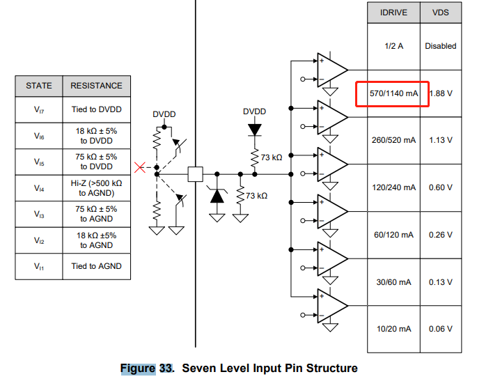
       My ctm uses DRV8320H (Hardware Interface) in BLDC application. The drive current(570/1140mA) is not enough for their application while they set pin-IDRIVE in VI6 State. They also don't want to set it in VI7

state. Because the VDS is disabled in VI7 state and there is no OVP for mos. They hope TI can offer a  DRV8320H equation that can deduce the relationsip between the three(Pullup resistance / IDRIVER / VDS) so that they can use a pullup resistance smaller than 18kΩ which can let the device offer a driver current higher than 570mA/1140mA and a effective VDS voltage. Thank you !

  • Hello Troyson,

    I'd like to apologize for the delay as a result of the holiday season. An expert has been notified and should follow up with you early next week if you have any questions.

    To start, I'd like to clarify that the IDRIVE and VDS settings are tied to separate pins on the DRV8320H device. This means, IDRIVE and VDS can be set separately to any value between VI1 and VI7.

    For example, the IDRIVE pin can be tied to DVDD to set the IDRIVE setting to 1/2A while the VDS could be tied to AGND to set the VDS threshold to 0.06V; which should achieve your goal.

    If you have not experimented with these settings before, I highly encourage you have resistor foot prints that are pulled up to DVDD and pulled down to AGND. This will allow you to experiment with different settings without having to change the layout. Otherwise, the DRV8320x-EVMs should be able to help you evaluate the settings as well

    Best,

    -Cole

  • Hi Cole,

             Thank you for your great support . My ctm still needs you offer the exact equation so that they can set the safety value of pull-up resistor rather than setting an unsafety value that may causes OVP offed. Thank you !


  • Hi Troyson,

    The configuration inputs for the DRV8320H have 7 discrete levels; there is no equation that can be used to set intermediate levels. Therefore, as the only IDRIVE setting higher than 570/1140mA is 1A/2A, the customer will need to tie the IDRIVE pin directly to DVDD to set the DRV8320 to this drive strength.

    The VDS level is set by the pull-up/pull-down resistor connected to the VDS pin, which is entirely separate from the IDRIVE pin. The customer can use any setting from VI1 to VI6 to keep VDS protection active. To determine which threshold to use, the customer should look at the max RDSON of their planned MOSFET and the max current flow expected from the system.

    Thanks,
    Garrett

  • Hi Garrett,


            Got it. It can solve the issue. Thank you!