This thread has been locked.

If you have a related question, please click the "Ask a related question" button in the top right corner. The newly created question will be automatically linked to this question.

DRV8873: DRV8873

Part Number: DRV8873

Hi,

I want to change the drv8432 to drv8873 to get cost down.

I know drv8873 has 10A peak current but there is no any spec of contineous current in the data sheet.

May be, it depend on how to adjust the heat think for the chipset.

I want to get high current .. countineous 4 ~ 5A but the package is so small.

Even though its peak  current spec is 10A, I wonder if it is possible to get 5A.

So I purcharsed the EVM kit from TI site. it doesn't arrive at me yet.

I hope that anyone advise to my plan.

  • KW,

    The continuous output current capability is related to the board thermal performance. The thermal performance is decided by PCB layout; ambient temperature; PWM frequency... To evaluate or estimate the thermal performance, please set the maximum input voltage; maximum PWM frequency; highest ambient temperature. And then, run your board to see at what is the maximum load condition when the board or DRV8873 gets the maximum allowing temperature?

    Also, if you know the thermal resistance and the device temperature, you can estimate the DRV8873's power loss at that certain load condition.


  • Thank you for your helpness.

    First of all, I will try to check the thermal condition wth the EVM kit.

    It has arrived at my office this evening.

    thank you ..


  • Yes. That is a good starting point.

  • Hi, Wang Li

    The EVM Kit (DRV8873H-Q1EVM) has been in my lab.

    It is working well.

    This time, I have some questions for the current sensing function of the driver chip.

    According to the data sheet as blow as,

    ###############

    8.2.1.3 Sense Resistor
    For optimal performance, the sense resistor must have the following features:
    • Surface-mount device
    • Low inductance
    • Placed closely to the motor driver device
    Use Equation 10 to calculate the power dissipation (PD) of the sense resistor.
    PD = (I(RMS) / k)2 × R(SENSE) (10)
    In this example, for the RMS motor current is 2.5 A, the sense resistor of 1.5 kΩ dissipates approximately 7.5
    mW of power. The power quickly increases with higher current levels. Resistors typically have a rated power
    within some ambient temperature range, along with a derated power curve for high ambient temperatures. When
    a PCB is shared with other components that generate heat, the system designer should add margin. Measuring
    the actual sense resistor temperature in a final system is best.

    ################

    at the Equation, PD = (I(RMS) / k)2 × R(SENSE)

    I think that the voltage at the Rsense resistor is about 3.3V, at 2.5A load current, R is 1.5K.

    if it is right, I could prob the voltage with scope.

    But there is no voltage out on the condition with my EVM kit.

    The pin number is 10 and 12 each other. the names are IPROPI1 and IPROPI2.

    The voltage is tested by multimeter.

    I don't know why the voltage is not out from the chipset.

    can you give me any tip for it?

  • KW,

    Can you measure the winding current and IPROPIx signal in a same scope? I would think the IPROPIx voltage low may caused by low winding current or a narrow current pulse.

  • Wang,

    What does the winding and narrow pulse mean?

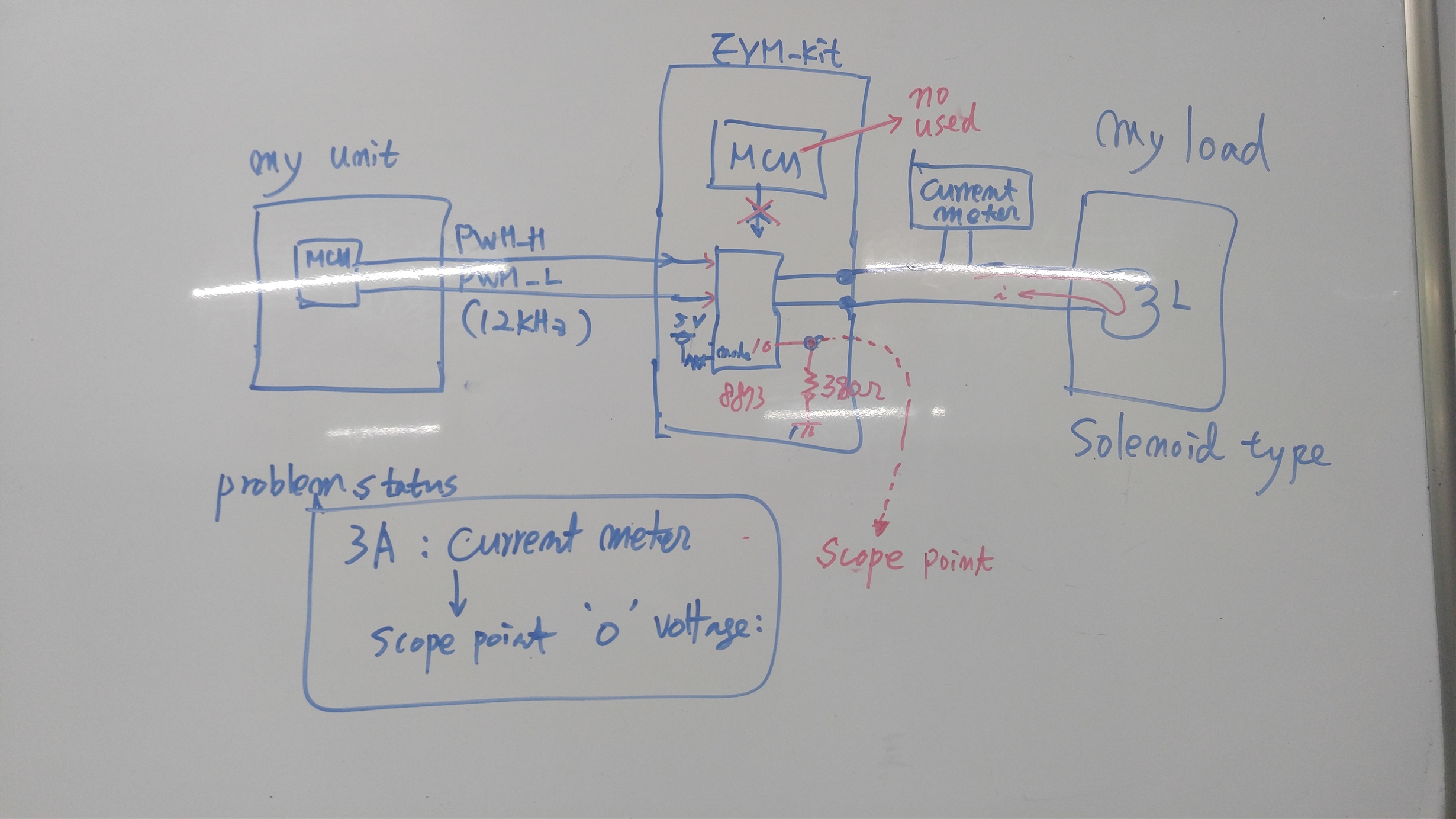
    Does the narrow pulse mean pwm pulse? PWM frequency is 12KHz. about 80usec period.

    I don't know what the winding' mean is. The load is a coil of solnenoid type.

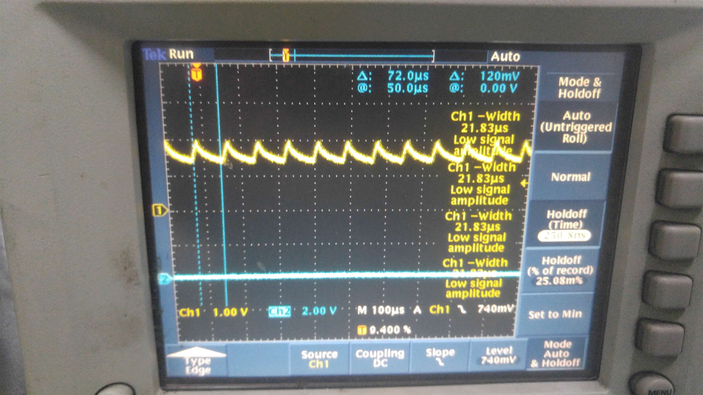
    Refer to my test bed capture.

    1. current wave capture

    2. test bed block


  • KW,

    1. IPROPIx reflects the high side FET current.

    2. What SR setting do you have? From your test waveform, the solenoid winding current goes up sharply (maybe only few us). If SR setting is too low, IPROPIx may miss that current info.

    3. How do you drive the current going up sharply and going down slowly? If the solenoid winding current in falling period doesn't go through the high FET. IPROPIx doesn't have output.


  • Hi, Wang,

    After I changed SR to NC state(High Impedance), the sensing wave was out.

    Refer to captuer wave.

    But it seems to be difficult for me to use the sensing signal for my unit.

    because the signal is pulse wave, to use it, it must be synchronized to PWM pulse.

    if we make it to flat by using low pass filter, it is possible to use it for my unit.

    So I have to use other sensing function, for example, a effective hall sensor(ACS724).

    Anyway, thank you again for your helpness.

    good luck..

  • KW,

    Do you turn on both low side FETs to make the current down? If you do, would you turn on both high side FETs to let the current go down. 

    IPROPIx reflects the high side FET current. So, I want the current going through the high FET as much as we can.