This thread has been locked.

If you have a related question, please click the "Ask a related question" button in the top right corner. The newly created question will be automatically linked to this question.

DRV8832: Regarding PWM on other signal

Part Number: DRV8832
Other Parts Discussed in Thread: DRV8837

Hi,

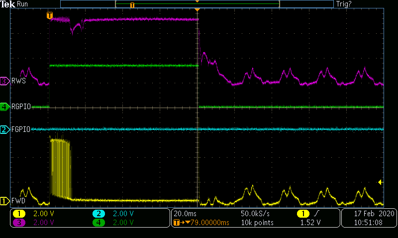
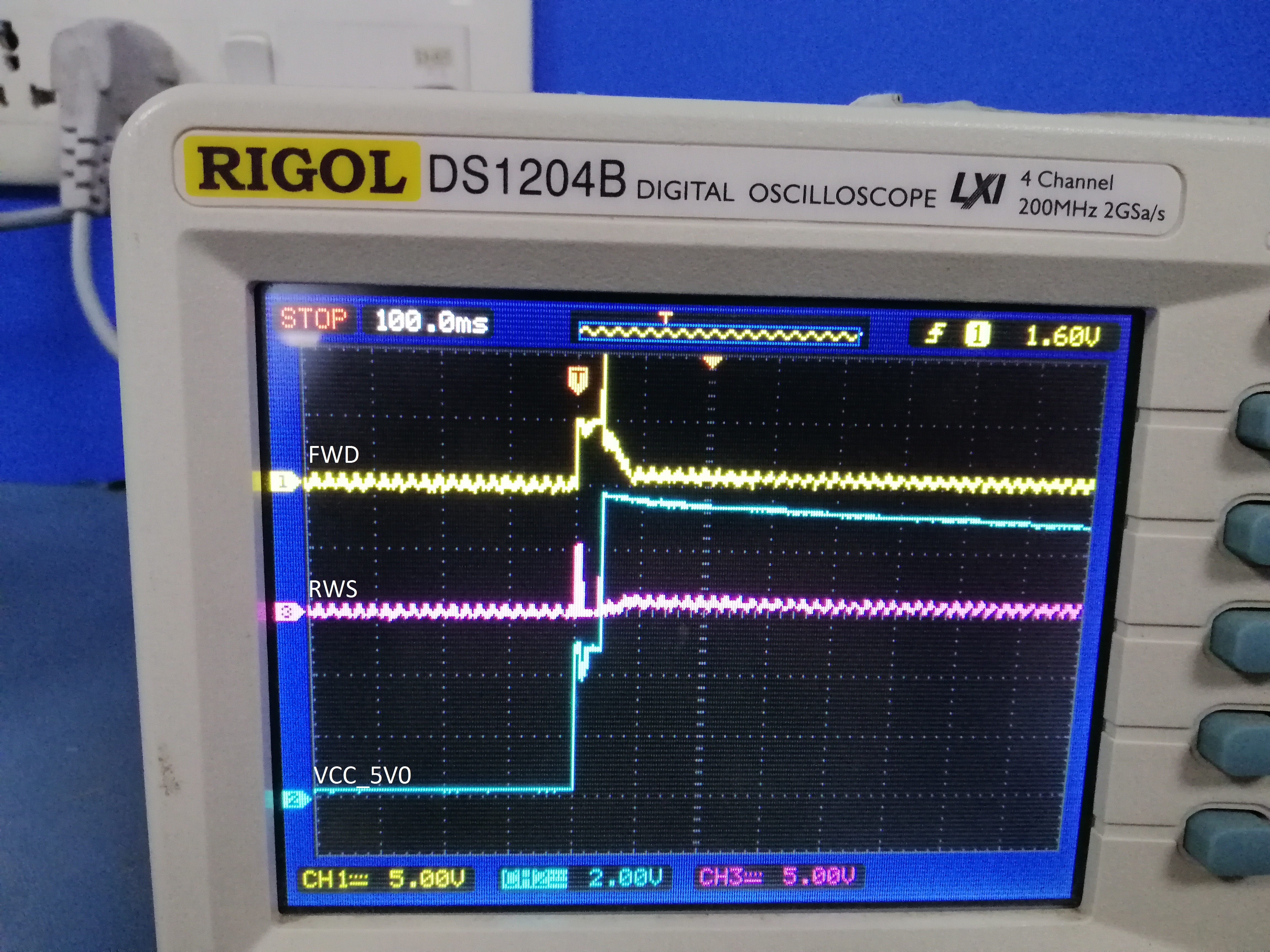
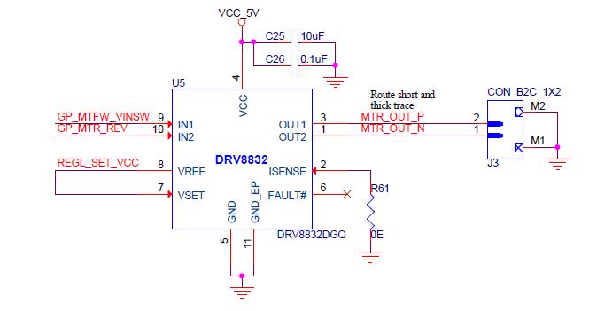
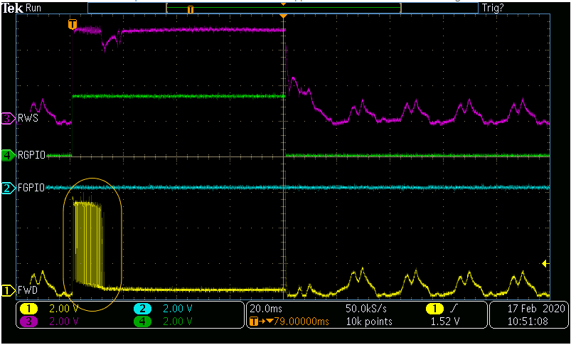
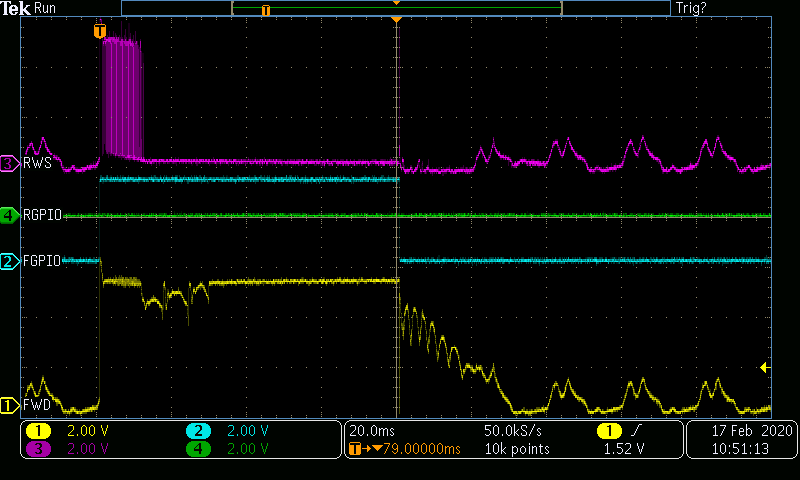
We are using "DRV8832DGQ" Motor driver IC in our design. We have seen PWM on other signal on other when we are keeping one signal as logic high.

Please let us know the reason why these PWM is occuring?

whether after 12msec actual signal will start? Attached waveform for your reference

  • Hi Manojkumar,

    The outputs will PWM to provide the proper voltage across the motor.

    If VCC is higher than 4 * VSET, the outputs will be PMW'ed. If VCC is less than 4 *VSET, the outputs will not be PWM'ed.

    Please see Figures 10 through 14 of the datasheet as an example.

  • Hi Rick,

    Thanks for reply.

    In our case we have tied Vref to Vset and Vcc is 5V. 

    For our application we need 80 msec enable pulse to move motor, where as we have seen some times motor stuck. Is This PWM will make any cause in output?

    Below are my circuit and waveform captured

    There is dip in IN1 after this 12 msec PWM. Please help

  • below is my circuit.

    Observed voltage dip at IN1 after 12 msec PWM and some times we have observed motor stuck. Whether this Output PWM will make any cause.

    Please help

  • Hi Manojkumar,

    Can you provide a cross reference between the names of the scope capture signals and the nets on the schematic?

    Scope Capture      Schematic

    RWS                      GP_MTFW_VINSW

    Can you add a pullup resistor on FAULT# and monitor the signal when the motor is stuck?

    Also please provide a scope capture of VCC when RWS is drooping.

  • Hi,

    Please find below for cross reference of names which we have used

    Scope: RWS: Pulse captured during motor reverse direction(J3.1)

    Schematics:GP_MTFW_VINSW: Forward GPIO(i have mentioned FGPIO in scope)

    Below is the waveform for VCC when there is voltage drop

    Please Note motor stuck is very rare and we wanted to understand reason.

    VCC_5V0 is generated from LDO(9V to 5V) where 9V is battery

  • Hi Manojkamar,

    Thank you for the additional information.

    There does not appear to be a reason for the motor to stick. Since it is rare, please try to determine if the motor position at start up is causing the sticking.

    It is also important to look at the waveforms (including FAULT#).

    If you have motor current information during the sticking event, please provide it.

    When the motor sticks, is a power cycle or sleep entry/exit required? This is an indication of too much current causing an overcurrent fault.

    Also, please note the droop on VCC is likely the cause of the droop on FWD.

    And the spike on VCC to 9V should be addressed. This is above the 7V abs max of the device. Additional bulk capacitance or a zener to GND may be required.

  • Part Number: DRV8832

    Hi,

    We are using "DRV8832" for our application to drive 5V DC motor with 80 msec pulse. Where as while applying high on IN1 observed 12 msec PWM on IN2. Please let us know the reason why this is getting appeared.

    Please find below waveform, we are giving 80 msec pulse and after PWM only waveform is stable. Please help in this

  • Manojkumar,

    Did you use an EVM or your own board to do the test?

    The datasheet "7.3.2 Bridge Control" section explains the 12ms PWM duty cycle ramp-up time: " Note that when transitioning from either brake or sleep mode to forward or reverse, the voltage control PWM starts at zero duty cycle. The duty cycle slowly ramps up to the commanded voltage. This can take up to 12 ms to go from sleep to 100% duty cycle."

    This is like the output voltage/current soft start control.

  • Hi,

    Thanks for the detailed reply. 

    In our application we have tied VREF to VSET and Vcc is 5V. As per the first statement if VCC is less than 4*VSET(4*1.33=5.32) output should not be PWM'ed.

    But still we are seeing PWM. I have also reduced VCC to 4V and tried. Still PWM is occurring. Kindly help

  • We have used our own board. Following is my circuit.

    We have shorted Vref to Vset. As per above condition PWM should not appear on IN2. but here PWM is occurring. Please let us know the reason

  • Hi Manojkumar,

    If you are referring to the 12ms of PWM at the beginning (circled area below), this is how the device operates.

    From section 7.3.2 of the datasheet:

    When both inputs are low, the output drivers are disabled and the device is placed into a low-power sleep state. The current limit fault condition (if present) is also cleared. Note that when transitioning from either brake or sleep mode to forward or reverse, the voltage control PWM starts at zero duty cycle. The duty cycle slowly ramps up to the commanded voltage. This can take up to 12 ms to go from sleep to 100% duty cycle. Because of this, highspeed PWM signals cannot be applied to the IN1 and IN2 pins. To control motor speed, use the VSET pin as described below.

    If you do not want the PWM'ing at the beginning of the cycle, please consider using the DRV8837 as an alternative.

  • Thanks for the reply.