This thread has been locked.

If you have a related question, please click the "Ask a related question" button in the top right corner. The newly created question will be automatically linked to this question.

DRV2511-Q1: Noise occurs during vibration

Part Number: DRV2511-Q1

Hi team

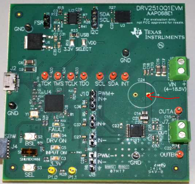
Our team are investigating the DRV2511 with DRV2511EVM.

When we observe the voltage&current of vibration waveform of DRV2510 with an oscilloscope.

We found obvious noise when DRV2511EVM turn on in GUI(which makes the LED of DRV_ON ON).

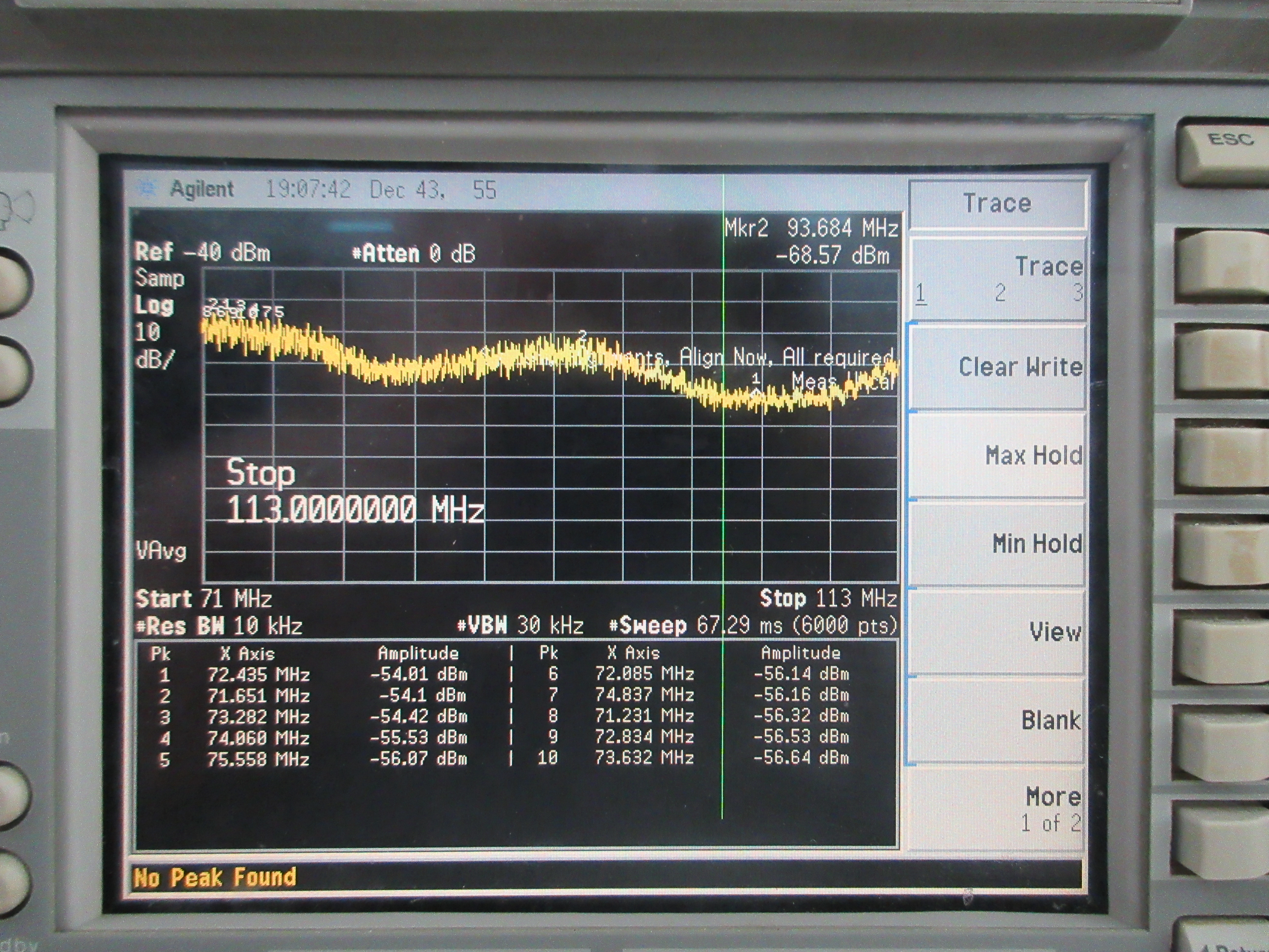
And we measured the frequency of the "noise", that we found the frequency equals the internal oscillator frequency of DRV2511.

So we think the source of this noise are from DRV2511 itself.

we don't understand why the noise occur, and could you help to give any advise to resolve this noise?

Best regards,

Yun Lin

  • Hi, Yun,

    Could you take a look at this e2e thread and test the recommendation about the reserved register, please?

    https://e2e.ti.com/support/motor-drivers/f/38/t/838426

    Please let me know if the problem persists.

    Best regards,
    Luis Fernando Rodríguez S.

  • Hi Luis,

    So thanks for your kind mention.

    However our team are testing the DRV2511, not DRV2510.

    I don't think the problem can be solved because of the setting of reserved register.

    Our team have a so serious problem about the EMI of he DRV2511.

    We have done the evaluation of radio frequency noise, 

    and the noise are so obvious that our team are afraid this will affect the ECU performance.

    By the way,

    our team used spectrum analyzer in conduction method with a voltage probe,

    we tested the power supply line of J5 of DRV2511-Q1EVM

    • we have also added an extra/ external pi-type filter composed of a 47uH inductor and two 220uh capacitors.
    • Even if we halted the PWM signal inputted to IN+ and IN- port, which means there is not any vibration and output current

     unfortunately, above all we have done, the noise could not be resolved.

    Could your team give any advice to help us. 

    for example, how to build a proper the low pass filter to remove the noise, and whether there are any recommend land pattern that can help our team team to design the PCB that avoid the EMI problem.

    Best regards.

    Yun Lin

  • Hi, Yun,

    If you isolate the device from the rest of the circuitry in the board, do you still have this issue? If you also use a different power supply to power on the DRV2511, do you see this noise content?

    In order to provide a filter suggestion, we will need to have details about the possible root cause and the noise response (a FFT would be useful to understand the noise characteristics).

    Any other information you could provide will be appreciated.

    Best regards,
    Luis Fernando Rodríguez S.

  • Hi Luis

    There are two pictures of resut of the spectrum analyzer when our team do the noise test.

    The picture 1 was taken when all the devices got ready to power on except for the enable port of haptic driver IC was low, which is meaning the driver IC was inactive.  

    As you see, the floor of noise seems okay and there is almost not any obvious spike.

    Then, we pull up the enable port the driver IC.

    And the noise had get so seriously as the picture2 

    Picture 1

    Picture 2

    Above all, our team thought the resouce of the noise may be the driver IC.

    By the way,

    12V battery that is usually used for autmotive was used for haptic IC driver, and we do the conductive noise test on the wire between battery and haptic IC.

    A 5V regulator IC provides 5V to pull up enable port to make the IC active.

    Could you give us some suggestions so that we can overcome this issue

    Best regards,

    Yun Lin  

  • Hi Luis,

    Could the butterworth low-pass filter could solve the conductive EMC problem, which happened to DRV2511

  • Hi, Yun,

    Sorry for my late reply.

    Regarding the switching frequency issue, have you tested different switching frequency values with FS0, FS1 and FS2 to see if the noise level issue follows the switching frequency?

    In addition, could you add a low-pass filter for frequencies above the switching frequency and see if there's a better response? 

    Best regards,
    Luis Fernando Rodríguez S.

  • Hi, Luis,

    Our team have do some struggle wished to resolve this issue of EMI.

    • We changed the number of frequency inside the driver IC of DRV2511 and DRV2510,

    Unfortunately, there is almostly not any obvious difference of noise level.

    • We added a (unmounted C24 as below PCB) Al-condenser which has comparative high capacitence as 220u,

    however it seems that the added condenser can not help to lower the noise level 

    •  We cutted off the power line at the place of the red arrow as below, and insert a inductor of (range of 100u 47u 16u 1.0u )

    to bridge the cutted land pattern of power line to build a pi-typed low pass filter. We hope that will work well to remove the noise,

    in the end, there was no improvement of this issue either.

    • We also added the unmounted resistors(R17, R18) and condensers(C33, C34) to output side, but these components seems no helpful. 

    Above all, oure team have not found a certain method to take off the noise issue.

    What do you think about this issue, actually we don't make clear the mechanism of it. 

    We even can not judge which mode (normal or common) the noise is.

    Do you have any advise that can help us to make clear what the mode of this issue.

    And do you consider whether the recommend optional EMI filter of output path can help us.

    If we have to introduce this filter components to our electronic circuit, how can we select the components of C and L,

    I mean how to decide the ω0, If it is 400K(or 500K) multiple 2times π

    Best regards

    Yun Lin

  • Hi, Yun,

    Could you try with an output filter with 20KHz or 30KHz as Wo value, please? This should be enough to reduce the switching frequency noise.

    Best regards,
    Luis Fernando Rodríguez S.

  • Hi Luis,

    Thank you for your mention about the output filter,

    Our teem will try that, and feedback the result to you.

    By the way, can we know the reason why the frequency for the caculation is 20~30KHz instead of 400KHz~1.2MHz.

    Best regards,

    Yun Lin

  • Hi, Yun,

    The 400KHz is the switching frequency of the device, but the useful signal is not in this frequency range. The filter must be adapted depending of your input signal. What is the input signal frequency range that you will use in your design?

    Best regards,
    Luis Fernando Rodríguez S.

  • Hi Luis,

    I'm so glad to have your kind answer.

    Our team are planning to utilize a signal of 50KHz or 100KHz for input side.

    Best regards,

    Yun Lin

  • Hi Luis,

    Unfortunately, even if there is not any vibration, which means we don't input signal to DRV2511 or DRV2510 haptic IC, the noise was observed by spectrum analyzer.

    Therefore, we don't think this issue is as a result of the input signal.

    Does that mean we want to tune the filter to be useful in the switching frequency?

    Best regards.

    Yun Lin 

  • Hi, Yun,

    In this case, you would need to detect which frequencies are related to the noise issue. You would need to adjust the output filter to pass only the bandwidth that you will use to handle your load. Please see the electrical specifications of your load and adjust the filter only to the frequencies that the load will use.

    Best regards,
    Luis Fernando Rodríguez S.