This thread has been locked.

If you have a related question, please click the "Ask a related question" button in the top right corner. The newly created question will be automatically linked to this question.

DRV8824: Driver motor has choppy run and irregular current draw

Part Number: DRV8824

We are students working on a project using two DRV8824 drivers to run two bipolar stepper motors. We made two pcb:s and one worked fine, the other one didn't. We have since made two more and the last one works decent. The problem with that one is that it doesn't run smoothly and has irregular, and quite high, current draw.

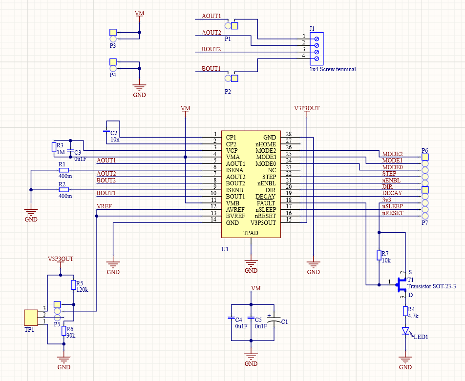
The reference voltage is where it should be according to the voltage divider, and no faults can be measured on the pcb. The potentiometer is 50kOhm and isn't connected, we tried removing it completely without any change in behaviour.

One thing to note is that we are running the motors on a slightly lower current than they can take according to their datasheet. Although this doesn't cause an issue on the other driver.

We are a bit stuck and don't really know what to try next to solve this.

Vref target = 0,66V

Rsense = 400m

Target current = 330mA

Decay: mixed

1/8 microsteps

Step frequency = 62,5 kHz

C1 = 100uF

Best regards, Adam

  • Hi Adam,

    The datasheet states a 0.47uF capacitor is needed on V3P3OUT. Please add one, and let us know if the issue is solved.

    If not, please provide scope captures of the currents of both working and non-working boards.

  • Hi,

    We tried adding a capacitor on V3P3OUT. It didn't change anything. Unfortunately we don't have access to a current clamp. The best we can do is an oscilloscope with regular probes. We did measure the voltage between one lead of the motor and ground. Please excuse the bad pictures, it was difficult to capture the bad behaviour. The good board had the same voltage plot as the bad one while working.

    There is however some new information. The previous board started out with a strange behaviour but often "mended" itself after a while. This new board worked fine at the beginning of the day. But then decided to start with it's strange behaviour. This started quite some time after adding the capacitor so the problems shouldn't be linked?

    Good:

    Bad:

    Best regards

    Adam

  • Hi Adam,

    I am assuming these boards are hand assembled. Is that correct?

    If yes, it is possible there could be some assembly problem (I have made plenty in the past). Please compare the good board and the bad board for differences at the pins of the DRV8824. It could be that after some time, heat in the system causes an intermittent connection.

    Also, what does the nFAULT pin look like on the good and bad board? A working board should have nFAULT at 3.3V.

  • Hi,

    We have compared the boards and can't see anything different. The good board and two of the bad boards including the current one has been through an oven. The last bad board was assembled by our professor.

    The nFault is always at 3.3V.

  • Hi Adam,

    Thank you for comparing the boards.

    There is obviously a difference between the two boards based on the scope captures.

    Can you please provide scope captures of the four output voltages (it looks like you have a four channel scope)?

    Ideally we would like jpeg or png images saved to the USB if possible (better quality), both at the original timescale above and zoomed in to help determine what is different.

    We may need more information later, but this should aid in debugging.