This thread has been locked.

If you have a related question, please click the "Ask a related question" button in the top right corner. The newly created question will be automatically linked to this question.

DRV2625EVM-CT: DRV2625 waveform issue

Part Number: DRV2625EVM-CT
Other Parts Discussed in Thread: DRV2625, DRV-ACC16-EVM

Hi, 

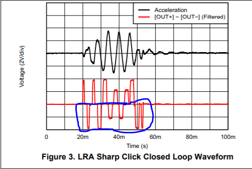
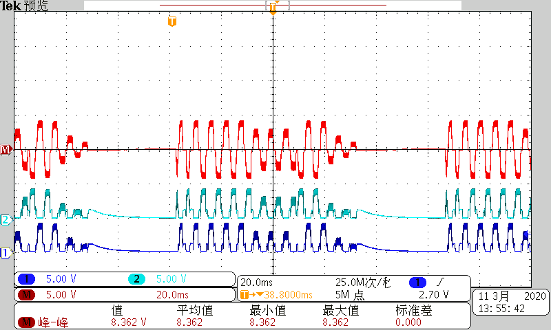
This is the DRV2625 test waveform, CH1 is acceleration waveform, CH2 is (OUT+) - (OUT-) waveform. CH1 seems fine, but CH2 seems abnormal. 

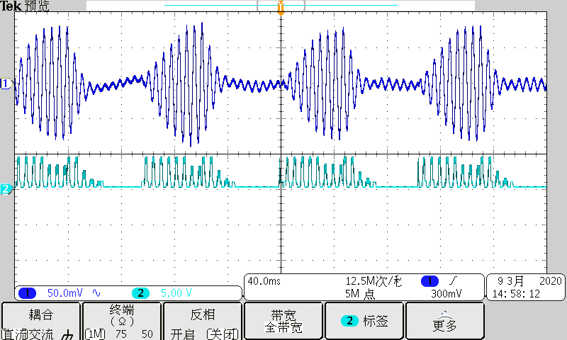
I'm not sure why the CH2 has no negative signal, Have you met this issue before? Maybe it's caused by probes and need differential probes?

Feel free to ask me if you have any questions or suggestions.

Thanks.

Best regards

Mason

  • Hi, Mason,

    Are you configuring the device in closed-loop mode? In this mode, the negative signal and zero can be used to brake the signal. In addition, if you have the AUTO_BRK_INTO_STBY set to '1', the part will go into brake mode before going into standby. This means that no negative signal will be needed.

    If the device is set in open-loop mode, you will strongly need of a negative signal to brake the device.

    I hope this helps you. Please let me know if you need additional support on this.

    Best regards,
    Luis Fernando Rodríguez S.

  • Hi Luis,

    Thanks for reply.

    I check the code, this device is in closed-loop mode and  AUTO_BRK_INTO_STBY isn't set.

    And i check the waveform in the EVM user guide, compared to my test waveform, blue circle part disappeared. And i still can't get the connection between this issue and the configuration. I think it might caused by other factors.

    Really appreciate it if you could help on this.

    Thanks.

    Best regards

    Mason

  • Hi, Mason,

    Thank you for your response.

    Do you have waveform captures of the independent OUT+ and OUT- (not the difference OUT+ minus OUT-)?

     Are you using our Haptics Control Console? If not, could you compare the results with this tool?

    Could you share the settings that you are using?

    Best regards,
    Luis Fernando Rodríguez S.

  • Hi Luis,

    Finally, i can get the waveforms correspond with datasheet.

    Below is the waveforms, CH 1 is OUT-, CH2 is OUT+, and the CH M(red) is OUT+ minus OUT-(calculated by oscilloscope).

    I reconsider the former issue, i connect CH1 probe GND to DRV-ACC16-EVM's GND, CH2 probe GND to DRV2625 board OUT-, which is not stable, CH1 probe GND and CH2 probe GND might have a conflict, might cause the waveform distortion. 

    Thanks.

    Best regards

    Mason