Hi Sir,
Pls kindly help to explain why scope got reserve current when motor STOP? (DRV8814 control DC Motor)
Thanks, Ian.
This thread has been locked.
If you have a related question, please click the "Ask a related question" button in the top right corner. The newly created question will be automatically linked to this question.
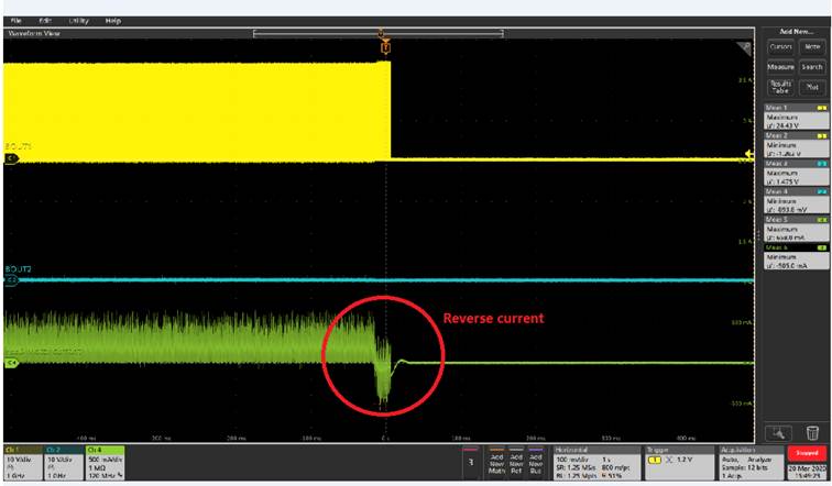
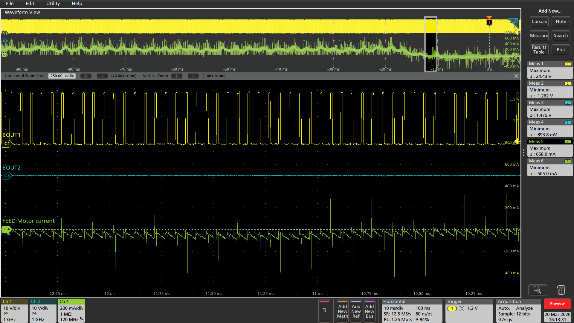
Hi Sir,
Pls kindly help to explain why scope got reserve current when motor STOP? (DRV8814 control DC Motor)
Thanks, Ian.
Hi Ian,
What are the four signals in the image?
Assuming channel 3 and 4 are inputs, please provide images of the output voltages instead.
Where is the current being measured?
Please zoom in further to the area where the current is reversing?
Hi Sir,
As shown below:
2 channel (FEED ECHY) and 4channel (Pick ECHY) are the signals fed back by the dc motor to the MCU.
1channel (FEED Motor current, BOUT1 signal of DRV8814PWPR ) and 3 channel (Pick Motor current, AOUT2 signal of DRV8814PWPR) output to control
different dc motors. We want to know why the reverse current is generated when the dc motor stops.
Pls kindly help to explain why scope got reserve current when motor STOP?
Thanks, Ian.
Hi Ian,
I really need the zoomed in voltages at the point where the current switches from positive to negative.
Please request these from the customer.
Also, please find out where the current is measured.
Hi Ian,
I can see that something is changing at the outputs but I cannot determine what is causing the change.
I have highlighted the area.
In this area, the voltage at BOUT1 is shifting up by a little. The peak is now higher and the bottom also is a little higher.
I am assuming the inputs may have changed to cause this.
What is changing in the system to create this higher voltage?
What is the DECAY setting?
A new scope capture of 2ms/div that shows the outputs shifting up, plus understanding how the inputs have changed will help.