This thread has been locked.

If you have a related question, please click the "Ask a related question" button in the top right corner. The newly created question will be automatically linked to this question.

DRV8350R: DRV8350R OCP Detection Start Time

Part Number: DRV8350R

Hi Team,

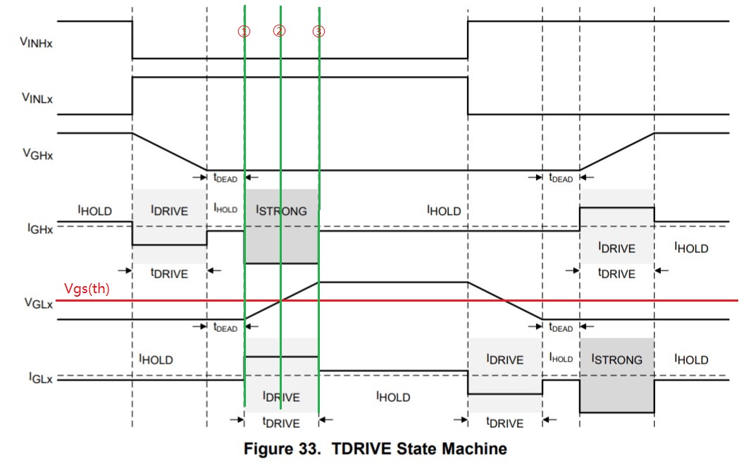
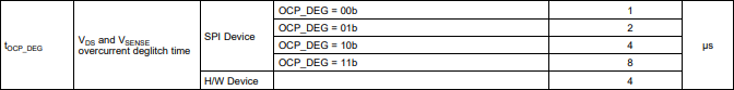
May I know when the OCP detection starts in the tDRIVE state machine?

Because it's found that there is there is some unexpected OCP when the source current is small.

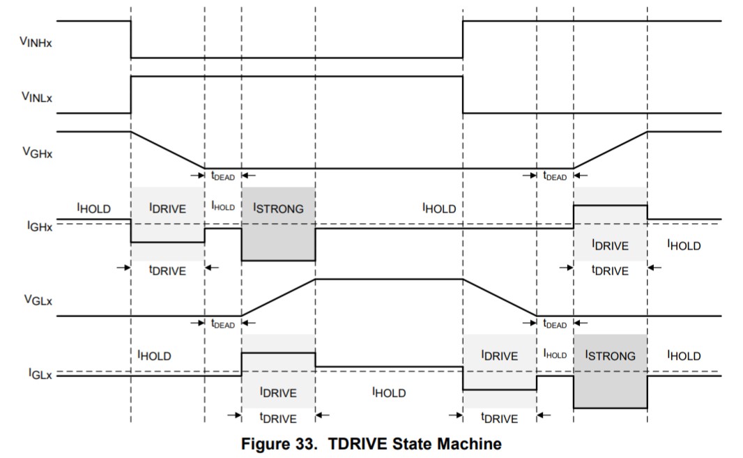
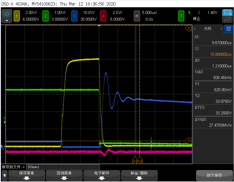
Here is the test condition, the IDRIVE is 50mA, tOCP_DEG is 1us, VDS_LVL is 0.7V, the waveform below is to for the low side PWM. It can be seen that there is fault. However, if the tOCP_DEG is increased to 4us, there is no fault; if the IDRIVE is increased to 300mA, there is also no fault.

So we suspect that when the source current is small as 50mA, the external FET is not fully turned on, so the Rdson is very large, although the Ids is small, it still triggers the OCP protection. Increase the tOCP_DEG or IDRIVE can solve this problem. 

So we wants to know when will the OCP starts work in the tDRVIE machine, it may better help understand this issue.

Yellow Line: Low side gate voltage 

Red Line: High side gate voltage

Green Line: Fault Pin voltage

Blue Line: Phase voltage

Thanks and Best Regards!

Hao

  • Hao,

    Your hypothesis sounds correct, I suspect that the longer deglitch time is allowing the VDS to settle so the VDS monitor is not faulting with the longer deglitch time or the stronger IDRIVE (stronger IDRIVE will help the VDS slew faster).

    The Deglitch time applies any time when the FET is ON so it makes sense that this could happen in any part of the waveform.

    Which FET is the customer using?

    Regards,

    -Adam

  • Hi Adam,

    How to understand "the FET is on", is it start to be turned on or fully turned on? I have drawn three green lines in the picture, could you please help confirm which line is the start time for the FET on?

    I have send the FET to to you email. Thanks!

    Best Regards!

    Hao

  • Hao,

    Actually I confirmed with my team that the OCP will start to monitor the output once the device recognizes the input (INHx or INLx) has become HIGH.

    There is some deglitch time for the output which is mentioned in the datasheet:

    Based on the FET information and assuming a typical requested rise time of 200nS, the IDRIVE setting of 100mA/200mA or 150mA/300mA (source/sink) should be selected.

    Regards,

    -Adam