This thread has been locked.

If you have a related question, please click the "Ask a related question" button in the top right corner. The newly created question will be automatically linked to this question.

DRV8874: DRV8874 Input Logic Hysteresis

Part Number: DRV8874

Hello team,

I would like to understand about Input Logic hysteresis on DRV8874.

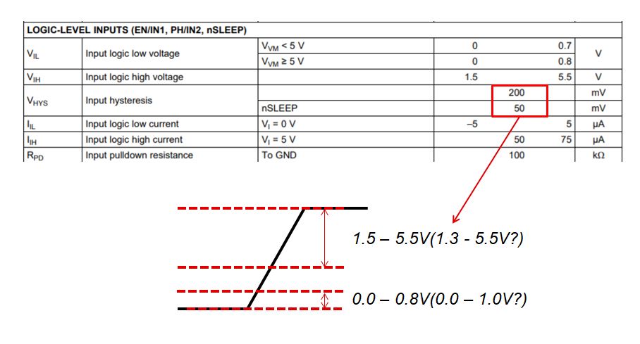
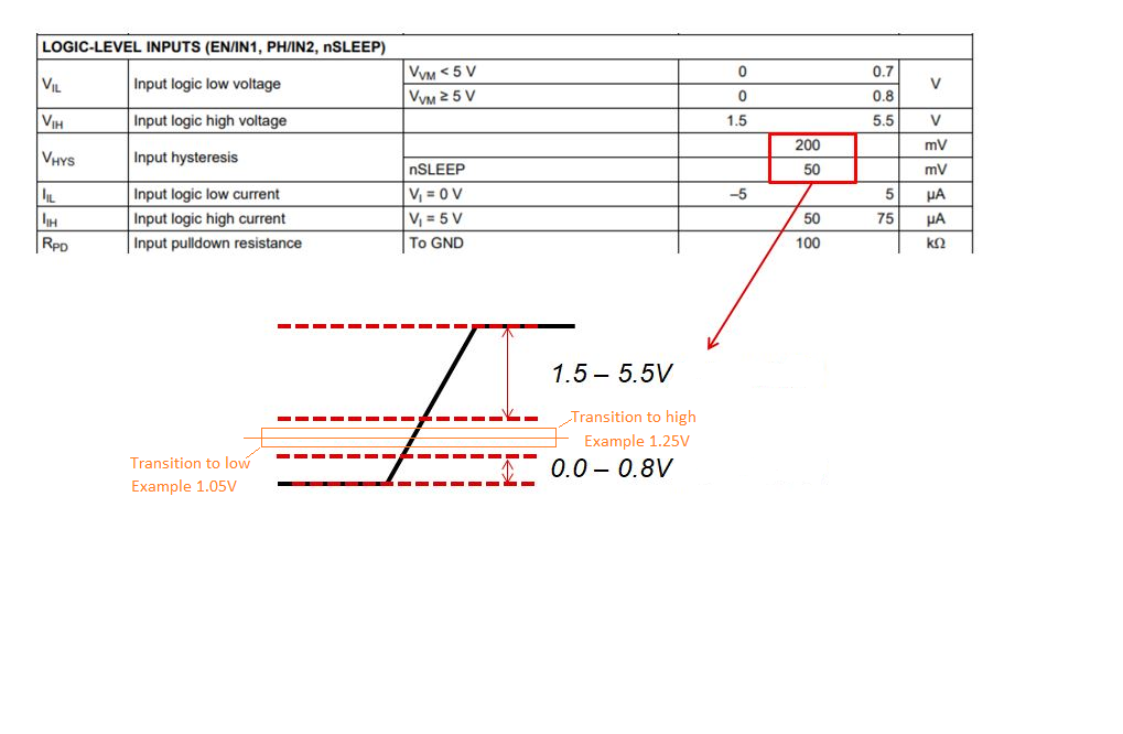
Attached is the image of my understanding of it so far.

Logic Low: 0 - 0.7Vor0.8V / Logic High: 1.5 - 5.5V

Hysteresis: 200mV means 

Logic Low:0 - (0.7or0.8V+/-0.2V) / Logic High: 1.5 +/-0.2V - 5.5 +/-0.2V ?

Please tell me how to consider the input level voltage.

Best Regards,

Kazuki Kitajima

  • HI

    if the input signal is less then 1.5 v it is called  0 logic

    if input signal is greater then 1.5 voltage then logic is 1

  • Hi Kitajima-san,

    Hysteresis is added to prevent input switching due to noise.

    Once the input has switched from high to low or low to high, 200mV is typically needed to switch the input back to the prior value.

    The VIL and VIH specifications of 0.7/0.8V and 1.5V do not change.

    As an example, please see the updated diagram below.

    The typical switching point for the EN/IN1 and PH/IN2 inputs is 1.25V for a low to high transition. Once the input reaches 1.25V, it must fall to 1.05V to be recognized as a low. The difference between the low to high transition value and the high to low transition value is the hysteresis (200mV).

  • Rick-san,

    Hope you are doing well.

    Thank you for answering and adding a diagram. Let me confirm and ask 3 things below.

    1: transition point isn't 0.8V/1.5V

    2: 1.25V transition point is an example. Is this spec value or just example?

    3: What would happen if EN signal is switching around this transition point during Tpd?

    For #2, the customer is considering if their EN input changes around this transition point during Tpd,

    the device doesn't work properly.

    Best Regards,

    Kazuki Kitajima

  • Hi Kitajima-san,

    Yes, I am doing well. I hope you are also.

    1: transition point isn't 0.8V/1.5V

    Correct -- the transition point is typically set to be in the middle of the range.

    2: 1.25V transition point is an example. Is this spec value or just example?

    Correct -- this is an example. The actual transition point moves from device to device with process and temperature.

    3: What would happen if EN signal is switching around this transition point during Tpd?

    For #2, the customer is considering if their EN input changes around this transition point during Tpd,

    the device doesn't work properly.

    The device may or may not work properly. In addition to the transition point, the DRV8874 has internal synchronizers that remove noise on the inputs.

    For #2, the customer is considering if their EN input changes around this transition point during Tpd,

  • Rick-san,

    Clear about transition point!

    One last question. Could you tell me about internal synchronizers?

    Is this like a digital filter?

    Best Regards,

    Kazuki Kitajima

  • Hi Kitajima-san,

    Yes, the internal synchronizers are like a digital filter.