This thread has been locked.

If you have a related question, please click the "Ask a related question" button in the top right corner. The newly created question will be automatically linked to this question.

DRV8874: application for dc brushed motor with current feedback loop

Part Number: DRV8874
Other Parts Discussed in Thread: , MSP-EXP430G2ET, INA194,

Good morning to all.

I would like develop  one new application to a DC brushed motor using DRV8874 integrated current sensor IC. Main objective is to implement current loop / torque loop using current sense output voltage across RIRPOPi resistor. My application needs bidirection control with speed variation with PWM control. I need current value will be compared then error should pass through PI controller then PWM signal.

Please suggest to the following questions.

1) Is there any application note to meet my application?

2)  For that application which control method is better PH/EN mode or PWM mode. what is the difference between these two modes.

3) Current sense  direction is always positive, irrespective of forward direction or reverse direction.. How to use in current loop for implementing PI controller.

 4) I designed values are : Rpropi= 1500 ohms, I TRip=4.835A, VADC requirement=3.3V, Vref:3.3V.

  • Hi Subbaraju,

    1) There is no application note.

    2) PH/EN is typically used because only one PWM resource is needed. When using PWM mode, two PWM resource may be required (assuming the PWM output cannot be routed to multiple GPIOs).

    3)The current is always positive, and only available when current is flowing from drain to source in the low side FETs. Since the mcu is controlling the current direction through the low, the voltage at IPROPI should match the direction of the inputs.

  • Subbajaru,

    1. Please check http://www.ti.com/lit/an/tida012/tida012.pdf It uses current sense resistor to sense the current, instead of DRV8874's IPROPI.

    2. PH/EN and PWM differences is listed in the datasheet.

    3. The controller has to control INx or PH/EN pin on top of the current loop to know it is forward or reverse direction.

    4. I don't see any issue with that setting.

  • Good morning ,

    Thank u very much . 

    I have seen tida012.pdf application note, very useful tome. I have a doubt i.e why do want to read DC bus voltage and where to used in the algorithm.Is it required in open loop control only.

    Coming to my project:

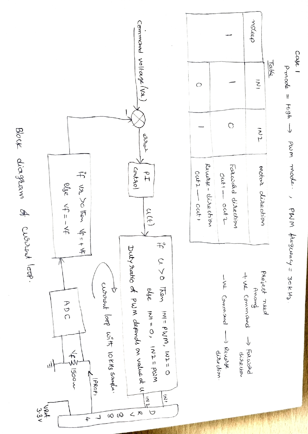
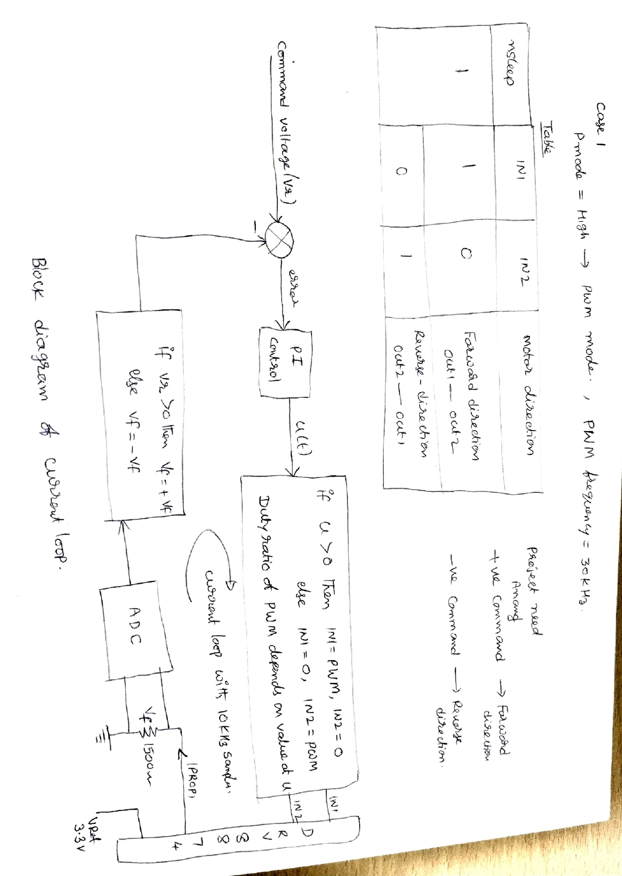
    1) I attached the file, having block diagram of current loop using DRV8874 IC. Please confirm block diagram is okay or not. I want to use for bidirectional motor control with low speed application ( <20rpm). I want to use in critical application where gimbals to be driven to keep camera maintain line of sight . 

    2) For this application Imode should be cycle by cycle control or fixed off time time control.

    3) is it required to measure DC bus voltage in closed loop application.

    Regards

    N subbaraju.

  • Hi Rich Duncan,

    Thank u very much.

    I want to implement based on your reply ( point 3), I proposed the block diagram for current loop using drv 8874. Please find the attached diagram. Is it okay or any suggestions please.

    Regards

    N Subbaraju

  • Hi Subbaraju,

    Conceptually, this appears to work.

    May I suggest you experiment with a DRV8874EVM?

    There are two methods available:

    1) Disconnect the mcu on the EVM and control the DRV8874 with the mcu of your choice.
    2) Re-program the mcu on the EVM. This requires some type of programming device such as a MSP-EXP430G2ET launchpad with appropriate cabling.

  • Hi Rick Dunkan,

    yes. I purchased DRV8874EVM and established the test up as follows.

    1) I removed the IN1, IN2  PWM potentiometers and interfaced with my mcu  DAC channels. with out disturbing the   msp430  and DRV8874 IC etc.

     Open loop motor is running in both directions nicely. For closed loop, I am reading V prop output with my MCU ADC  with 16 bit channel and implementing PI controller in my MCU . Present MCU allows 2000 samples per sec for current loop.  I have to do lot of experiments with test setup.  Due to lockdown, I unable do test now, I will udate later.

    But I have doubts.

    1) Weather DRV 8874 allows four quadrant operation or not?

    2) Weather I have to use PMode as PH/EN or PWM mode? 

    3)  How to ensure this device is working in forward braking and reverse braking quadrants. How to test or monitor the current during that time. Any application note?

    4) Between DRV8874PWPR and DRV8874 Q1 , which is latest and more qualified for production use?

    Thank u

    Subbaraju


  • Hi Subbraju,

    1) Weather DRV 8874 allows four quadrant operation or not?

    >> Yes, four quadrant operation is available. This assumes there is no violations of any absolute maximum values.

    2) Weather I have to use PMode as PH/EN or PWM mode? 

    >>> PWM mode allows more options (Coast mode is available in PWM mode, but not in PH/EN mode).

    3)  How to ensure this device is working in forward braking and reverse braking quadrants. How to test or monitor the current during that time. Any application note?

    >>> Monitoring current is possible if the current if flowing from drain to source in a low side FET. When using forward/reverse braking, there could be times when the current cannot be monitored. If current monitoring is required, adding an inline current sense amplifier like the INA194 may be required.

    4) Between DRV8874PWPR and DRV8874 Q1 , which is latest and more qualified for production use?

    >>> The DRV8874PWPR is the latest. Both are equally qualified for production use. The DRV8874-Q1 is intended for automotive applications.

  • Hi Rick Duncan

    Good morning,

    Regarding 3rd point, i have one doubt i.e

    3)  How to ensure this device is working in forward braking and reverse braking quadrants. How to test or monitor the current during that time. Any application note?

    >>> Monitoring current is possible if the current if flowing from drain to source in a low side FET. When using forward/reverse braking, there could be times when the current cannot be monitored. If current monitoring is required, adding an inline current sense amplifier like the INA194 may be required.

     Means, if I select PMODE = PWM mode and wants to drive in forward direction with duty ratio 25% ( ex Ton = 10micro sec, Toff= 30 micro sec) 

    Ton condition: nsleep= H, IN1= H, IN2=L for 10 micro sec then it rotate in forward direction, Iprop is available  ( current flows from LS source to drain)

    Toff condition: nsleep=H, IN1=L, IN2=L for 30 micro sec then it goes to coast phase, Iprop current is zero due to current flows from drain to source. Is it like that ?

    In that case , current discontinuity is there,  Shall I close the current loop  through this Iprop current and any problem?

    Similar issue will be there in reverse direction also.

    Regards

    N Subbaraju.

  • Hi Subbraju,

    3)  How to ensure this device is working in forward braking and reverse braking quadrants. How to test or monitor the current during that time. Any application note?


    You can start with this one:  

    >>> Monitoring current is possible if the current if flowing from drain to source in a low side FET. When using forward/reverse braking, there could be times when the current cannot be monitored. If current monitoring is required, adding an inline current sense amplifier like the INA194 may be required.

     Means, if I select PMODE = PWM mode and wants to drive in forward direction with duty ratio 25% ( ex Ton = 10micro sec, Toff= 30 micro sec) 

    Ton condition: nsleep= H, IN1= H, IN2=L for 10 micro sec then it rotate in forward direction, Iprop is available  ( current flows from LS source to drain)


    Correct, Ipropi current is available.

    Toff condition: nsleep=H, IN1=L, IN2=L for 30 micro sec then it goes to coast phase, Iprop current is zero due to current flows from drain to source. Is it like that ?


    Correct, Ipropi current is zero.

    In that case , current discontinuity is there,  Shall I close the current loop  through this Iprop current and any problem?


    If you use brake mode instead of coast mode during Toff, the Ipropi current remains available.
    If you need coast mode, adding an inline current sensor that can measure bidirectional current may be required.

  • Hi Rick Duncan,

    1) I would like to know about bulk capacitance in this design, generally we will follow  as thumb rule, 10 micro farad capacitor for 1A current.  EVM  bom suggested the capacitor part no : UBT1H101MPD1TD  ( 'CAP, AL, 100 uF, 50 V, +/- 20%, TH),. In our design height constraint is there, hence I would like to connect three capacitor in parallel, each 10 micro farad, part no:       597D106X9075R2T, from Vishay. Is it okay?  Please suggest any other guidelines.

    2) Two control two motors, we are keeping two DRV8874 ICs side by side with single set of bulk capacitance. Is it okay?

    3) Between DRV8874PWPR and DRV8874 Q1 , which is best for missile onboard systems?

    4) Thermal pad details please?

    Best Regards

    N Subbaraju.

  • Hi Subbraju,

    1) The EVM uses a capacitor based on the maximum current and lowest voltage.

    If you are using less than the maximum current and higher voltage, you may be able to reduce the capacitance.

    2) If only one motor is driven at a time, you should be able to use a set of capacitors to handle both.

    3) DRV8874-Q1 would be recommended. There is more information available about this device.

    4) The generic CAE/CAD files can be found here: 

    These files can be converted into multiple programs.