This thread has been locked.

If you have a related question, please click the "Ask a related question" button in the top right corner. The newly created question will be automatically linked to this question.

DRV8701: Current limiting failure with peltier modules

Part Number: DRV8701

Hello TI Support,

I am experiencing current limiting failures when driving two peltier modules (14.5V, 8.5A) hooked up in series with the DRV8701. Below is a schematic of how our IC is currently configured:

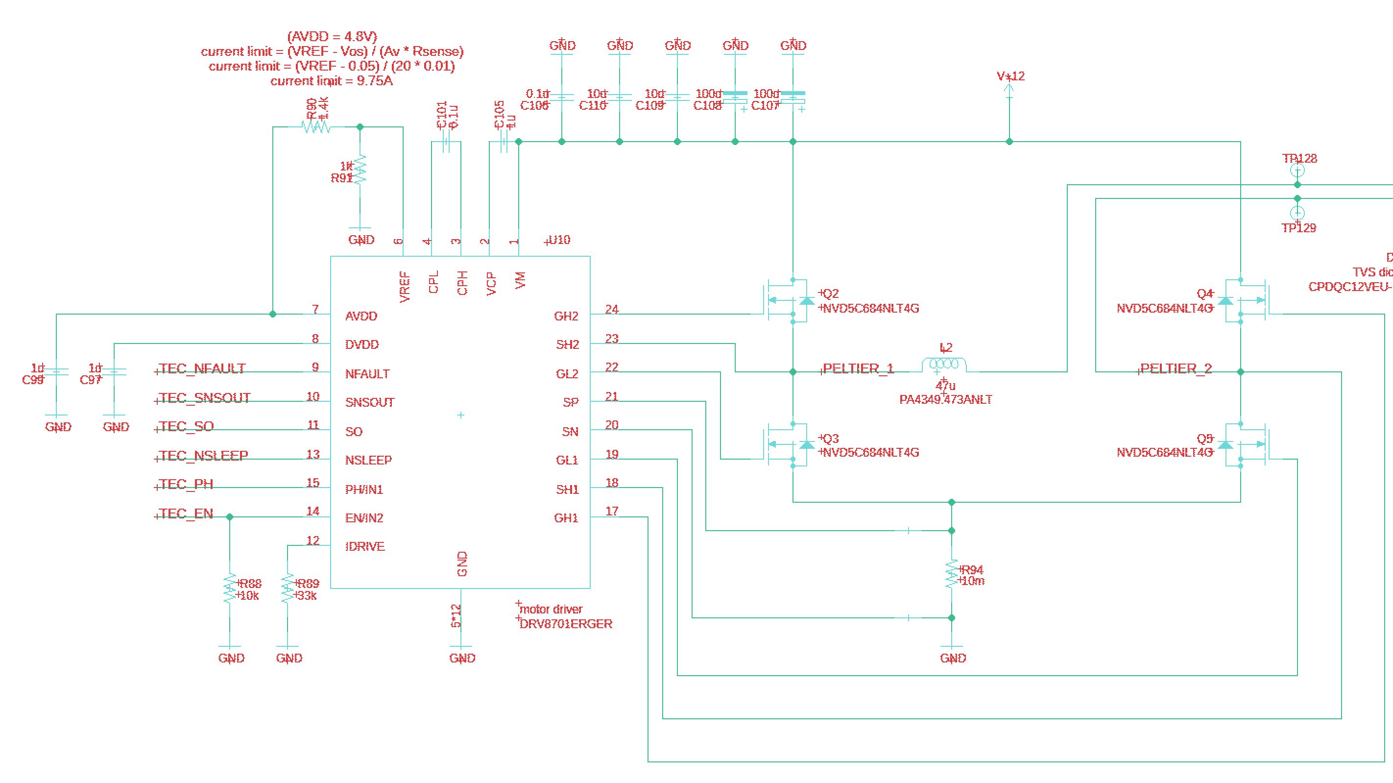
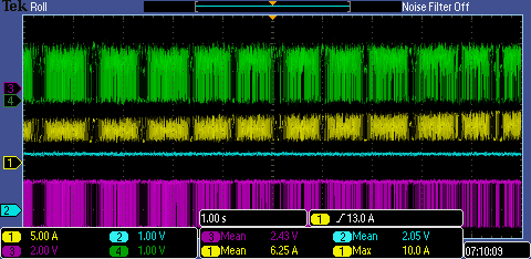
The current limiting failures are occurring at irregular intervals so it is difficult to pinpoint why it is failing and how we can optimize the design to ensure the current remains below 10A during regular operation.  In some instances the current limiting appears to be working and in other instances the current limiting attempts to chop before runaway.  Below are two oscilloscope images detailing the issue at hand both during normal operation and again during failure.

Yellow channel - Measuring current on 12VDC

Blue channel - EN (enable pin) 

Green channel - nFault

Purple channel - SNSOUT

Normal operation:

Failure:

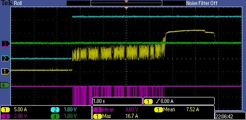
Is there a reason the SNSOUT remains high allowing the current to runaway as shown in the image above?  Any insight your team can provide would be greatly appreciated.

Thanks!

  • Hi Christopher,

    The schematic looks good. And based on the good waveform, there appears to be no reason for SNSOUT to remain high.

    Do you have multiple boards? If yes, do all the boards show this behavior?

    If only one board, please inspect the board again looking for possible residue between the pins.

    Can you move a few scope probes for additional debugging?

    First, set your trigger on current above ~13A to capture what is occurring on the following pins:

    1) VREF
    2) SO
    3) SNSOUT
    4) SP
    5) SN

    The first step is to probe where convenient. If you do not see any reason for the behavior, you may need to solder wires to the pins of the DRV8701.

    VREF and SO may provide the most information since these two pins directly influence SNSOUT. If either side of R91 becomes disconnected, this could explain the behavior.

    Please let us know what you find.

  • Hi Rick,

    Yes we have multiple boards and have experienced this failure on the two we have been testing thus far.  I inspected the board and performed a continuity test but I haven't noticed anything particularly abnormalities in the solder connections.

    Below are a couple more scope captures from yesterdays testing.  In both examples the green trace has been changed from the nFault pin to the SO pin and the blue trace has also been moved from the EN pin to the VREF pin.  The first image is what I believe is desired current limiting and the second image is where the pins begin limiting before  "remaining high".  Unfortunately my overcurrent issues happen infrequently so I was unable to capture any data of major spikes occurring last night although I had experienced at least two peaks in the 12-13A range when the pins were in this "stuck high" condition.


    We are both heating and cooling with our peltier modules so I am not sure if this has any effect into the typical operation of the current limiting digital logic within the IC.  Also, would it be preferable to change the hardware design so that we use a dedicated current limiting IC (or different driver chip better suited for pelts)?  Overall our design appears to be working as expected besides for these infrequent current spikes we have experiences as high as 18-21A which end up shutting down our 12V, 15A power supply.

    Your support is greatly appreciated.

    Best,

    Chris

  • Hi TI Support,

    One more interesting scope capture I forgot to attach.  This is when pins were all stuck in this "high position". 

    Green - SO

    Yellow - Current

    Blue - VREF

    Purple -SNSOUT 


  • Hi Christopher,

    There should be no reason for this behavior. Typical behavior is the device protecting itself.

    How many boards do not show this problem?

    Reviewing the schematic again, I noticed there is no connection shown to pin 16 and the thermal pad. Are this pins connected?

    Is it possible to get the layout? We can make arrangements to receive the data privately.

  • Hi Chris,

    Now that we are communicating privately, I will mark this thread as "TI Thinks resolved" 

    When we find the answer, I will post to the thread for all to benefit.