Hi All,
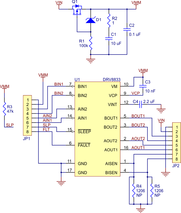
I built a small rover robot and I'm using the DRV8833 Dual Motor Driver Carrier from Pololu (see schematic at end of post) to control my motors. Initially I wrote a simple motor driver, that uses GPIO on my microcontroller to set AIN1, AIN2, BIN1 and BIN2 (0 or 1) as detailed in the datasheet (see Table 1).
So that worked great and was able to control the rover's movement (left, right, forward, backward), albeit these movements were all performed at 100% full throttle. I decided next to implement PWM so I could control the acceleration rate while speeding up and slowing down. I configured my microcontroller to put out a 16 KHz PWM signal and implemented logic to set run the motors forward/reverse in fast decay mode according to table 2.
I connected a logic analyzer to my motor driver inputs and outputs and verified I was getting the desired results (see below). As expected the output waveform was directly proportional to my input and the correct outputs were being enabled. I then reconnected my motors and was surprised to find that nothing happened (besides a high pitched wine). Being a bit confused I decided to try the slow decay mode and see if that had any better results.
PWM Control Fast Decay Mode (didn't work)
I then changed my logic so I would put PWM on one input and a logical 1 on the other pin, again according to Table 2 for slow decay. I once again checked the motor driver waveforms using my logic analyzer and was surprised to see the output waveform now is an inverted version of my input. Alas, I connected my motors and they actually ran, except now my speed up routine slows me down, and vice versa.
PWM Control Slow Decay (worked, but inverted PWM output)
So I have a few questions:
- Why wouldn't the fast decay PWM drive mode work? Especially since the output logic is correct to control the motor.
- Is the inversion from input to output expected when running the motor driver in slow decay mode?
- Am I doing something wrong here in the way I'm using PWM to control the motors?


