This thread has been locked.

If you have a related question, please click the "Ask a related question" button in the top right corner. The newly created question will be automatically linked to this question.

DRV8343S-Q1EVM: problem with current sense amplifier output

Part Number: DRV8343S-Q1EVM

Hello,

I have problem with internal Current sense amplifiers.
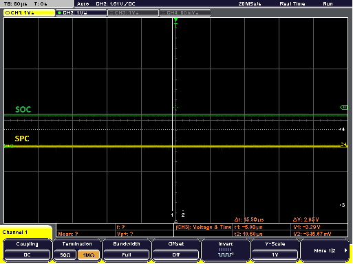
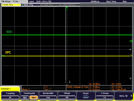
You can see pictures from Scope. There are input SPC and output SOC signals measured to SNC (GND).
After power up, everything is working. Pic 1: SPC = 0V, SOC = 1.2V
After Reset ( 1s low pulse on ENABLE pin) is the value of the SOC pushed higher. Pic 2: SPC = 0V, SOC = 2.1V
On Pic 3, it is closer look at the SOC value change.
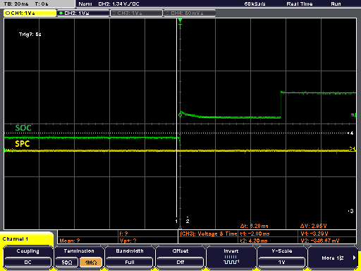
When is the level push higher, the value is incorrect, and the driver doesn't work.
Thanks for any advice.
Best regards Petr J.
  • Petr,

    Thanks for posting on the MD forum!

    Are you using the EVM as originally designed or did you make any modifications?

    Regards,

    -Adam

  • Hello Adam,

    Thank for your response. I just realize that I fill title wrong. It should be DRV8343SPHPRQ1.

    But the schematic is almost the same like EVM.

    VREF is power by 3V3 LDO.

    Best regards PJ

  • Hello PJ,

    What were the conditions of your application before applying the 1s low pulse on the ENABLE pin, i.e.GAIN, IDRIVE, VDS, and MODE?

    I have ordered an DRV8343S-Q1 EVM and am awaiting for it to arrive by tomorrow morning so that I can test your problem and try to replicate / debug the issue. 

  • Hi Aaron,

    gain - 20V/V
    iddrive - 200mA
    VDS - 0.45V
    mode - 6x PWM

    Regards PJ

  • Hi PJ,

    Could you provide a scope capture of SOC and VREF throughout the 1s reset pulse? Also, can you confirm if you're using bidirectional current sense operation?

  • Hi Aaron,

    We have same troubles with debugger, so I can’t send you scope pictures right now.

    But we try connect VREF over battery, for smoothest signal possible, with no change.

    Yes we are using bidirectional current sense (it is default).


    Regards PJ

  • Hi PJ,

    Can you confirm if there is any motor current flowing during testing? If VREF = 3.3V and SNC = SPC = 0V, then you should be seeing SOC be about 1.65V. Seeing SOC = 1.2V after powerup is too low if your VREF is 3.3V.

  • Hi Aaron,

    I attached scope pictures, there are: Enable, Vref, SOA, SPA signals, and time after SOA spike above 1/2 Vref (purple highlight).

    Vref = 3.32V

    SOA = 1,56V (before reset)

    SPA = 0V

    After Reset (Enable push to 0V) there is short voltage drop (grey highlight).

    All test are made with motor connected, before enabling PWM signals.

    Regards PJ

  • Hi PJ,

    Thank you for attaching scope pictures, this is interesting behavior.

    What is the CAL pin set to on your device? And are you performing any SPI operations after ENABLE goes high again? 

  • Hi Aaron,

    Cal pin is connected directly to GPIO pin on the processor (TMS320F28069MPZT).
    There is no SPI communication after reset.

    I have another Scope picture. It is very strange that Enable drops exactly the same time when power up auto calibration started.

    Regards PJ

  • Hi PJ, 

    From the image above, I am looking at a few areas of concern:

    1) CAL pin not reaching 3.3V when logic high & ENABLE dropping ~0.5V (might be a brownout condition with the 3.3V source)

    2) SOA reaching near ~3V, (i.e. current would be close to zero if in unidirectional mode or large amount of current is going through shunt resistor to SHx)

    Could I get more information on what you're using for the 3.3V regulator, and could you share that circuit? 

    I am also curious to see what happens if CAL is not asserted - does SOA behavior still occur?

    Finally, could you capture an SDO signal just to make sure SPI is working?

  • Hello Aaron,

    After reset, before SW fully starts, GPIO pins are pulled high (not high Z), and we had to pull them down. It caused the problem on Enable and CAL pins.

    We don't need manual calibration, so we disconnected this pin. For Enable pin we used 2k2 pull-down resistor.
    Also we sent SPI communication to much early after reset.


    Now we have all the signals in their correct state and everything works fine.

    Best Regards PJ