This thread has been locked.

If you have a related question, please click the "Ask a related question" button in the top right corner. The newly created question will be automatically linked to this question.

DRV8302: How to connect DRV8302 overcurrent protection circuit

Part Number: DRV8302

Hi Team,

The customer refers to the overcurrent protection circuit connected to the DRV8302 Datasheet, but obviously feels wrong. 

Adopt 1: 1 partial pressure (we use MOS tube R (on) = 3.6mΩ) current limit to 450A. In actual applications, such a large current is not reached, but an overcurrent error will still be reported. Is the customer understanding wrong? Can the overcurrent protection function be achieved by directly dividing the two resistors in practical applications?

Best Regards,

Annie

  • Annie,

    Please show us a diagram or schematic of the board you are using and let us know any settings that you have made.

    Regards,

    -Adam

  • Hi Adam,

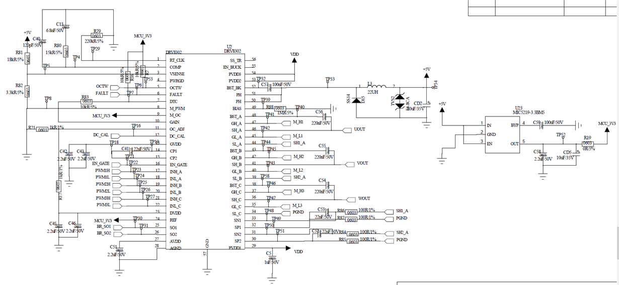
    I apologize for any delay in responding to your email. Customer provided the schematic just now.

  • Hi Adam,

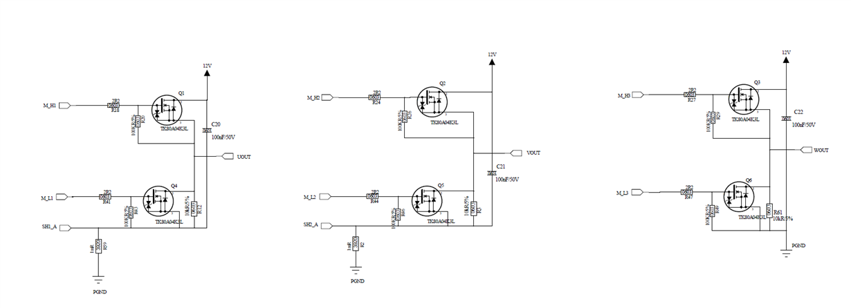
    Customer also attached MOS tube circuit.

  • Annie,

    Some comments on the schematic:

    1. SS_TR capacitor is missing.
    2. M_PWM has a resistor pull up and short to GND, is R82 populated?
    3. DC_CAL must be low for the sense amplifiers to operate, can you confirm this?
    4. BST caps are higher than the EVM.
    5. CSA input paths have 100 ohms on both the SN and SP lines, we do not recommend this, there should be no series resistance here.
    6. What is the purpose of R12?

    Likely the resistance in the CSA path is causing your issue.

    Regards,

    -Adam

  • Hi Adam,

    The following operations have been done by customer when trying the experiment current limit logic (R17 = 10k; R21 = 330R; calculated current limit 30A):

    1. Connect a power load (0.1R) between the AB two-phase outputs, collect current through an oscilloscope, control the A + B- conduction to grab the waveform, and display the current rises to about 26A to trigger protection, which is close to the theoretical value;

    2. The lower tubes (A-, B-, C-) are fully closed, there is no load between each phase, and only one upper tube (A +) PWM is turned on, then the protection is triggered after 2 to 3 PWM cycles;

    3. When the BLDC inductive load is actually connected, if the duty cycle adjustment increases too fast, nFault is also easily triggered;

  • Annie,

    These behaviors are expected, please let us know if you have any other questions.

    Regards,

    -Adam