This thread has been locked.

If you have a related question, please click the "Ask a related question" button in the top right corner. The newly created question will be automatically linked to this question.

DRV8847SEVM: Applying PWM signals to the input pins of DRV8847S for dual BDC motor

Part Number: DRV8847SEVM

Hi Team,

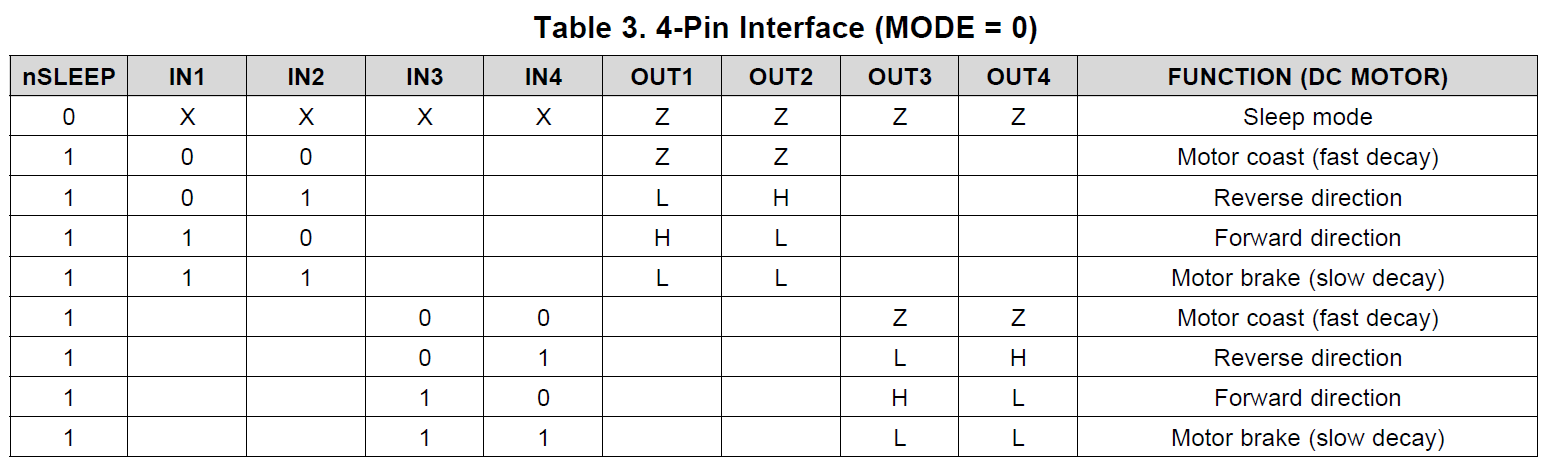
A customer is planning to use DRV8847S for dual BDC motor in 4-wire mode and applying PWM signals to the input pins for speed control. He wants to connect IN2 to GND and then apply a PWM signal to IN1 in order to control the speed of the motor. To reverse the motor and control the speed he wants to connect IN1 to GND and then apply PWM signal to IN2. Is this possible?

Regards, 

Danilo

  • Danilo,

    That works if you put the motor between OUT1 and OUT2.

  • Danilo,

    That works if you put the motor between OUT1 and OUT2.

  • Hi Wang Li,

    Thank you for your response. 

    Based on Table 3 of the datasheet, if IN1 is 0 and IN2 is 1 the BDC motor connected to OUT1 and OUT2 will rotate in reverse direction. However, if IN1 is 0 and IN2 is supplied with PWM signal from a microcontroller, the BDC motor will toggle between reverse direction and fast decay. In this situation, will the motor speed vary in proportion to the PWM pulse width or the motor will have unwanted vibration?

    Regards,

    Danilo

  • Danilo,

    The winding current is related to the winding terminal average voltage. if IN1 is 0 and IN2's PWM signal duty cycle higher enough, the motor speed varies reflect to the PWM pulse duty cycle (Ton/T). 

    If we assume the motor inductance higher enough, the winding current doesn't go to zero at end of fast decay.

    The average voltage on winding terminal is VM * (Ton-Toff)/(Ton+Toff). The motor speed will be proportional to this average voltage.

    Ton is IN2 half bridge's high side FET turn-on time, Toff is winding current going through IN2 half bridge's low side FET time.