This thread has been locked.

If you have a related question, please click the "Ask a related question" button in the top right corner. The newly created question will be automatically linked to this question.

DRV2700: Using DRV2700 as high voltage piezo driver, however, the output signal is incorrect.

Part Number: DRV2700

Hi,

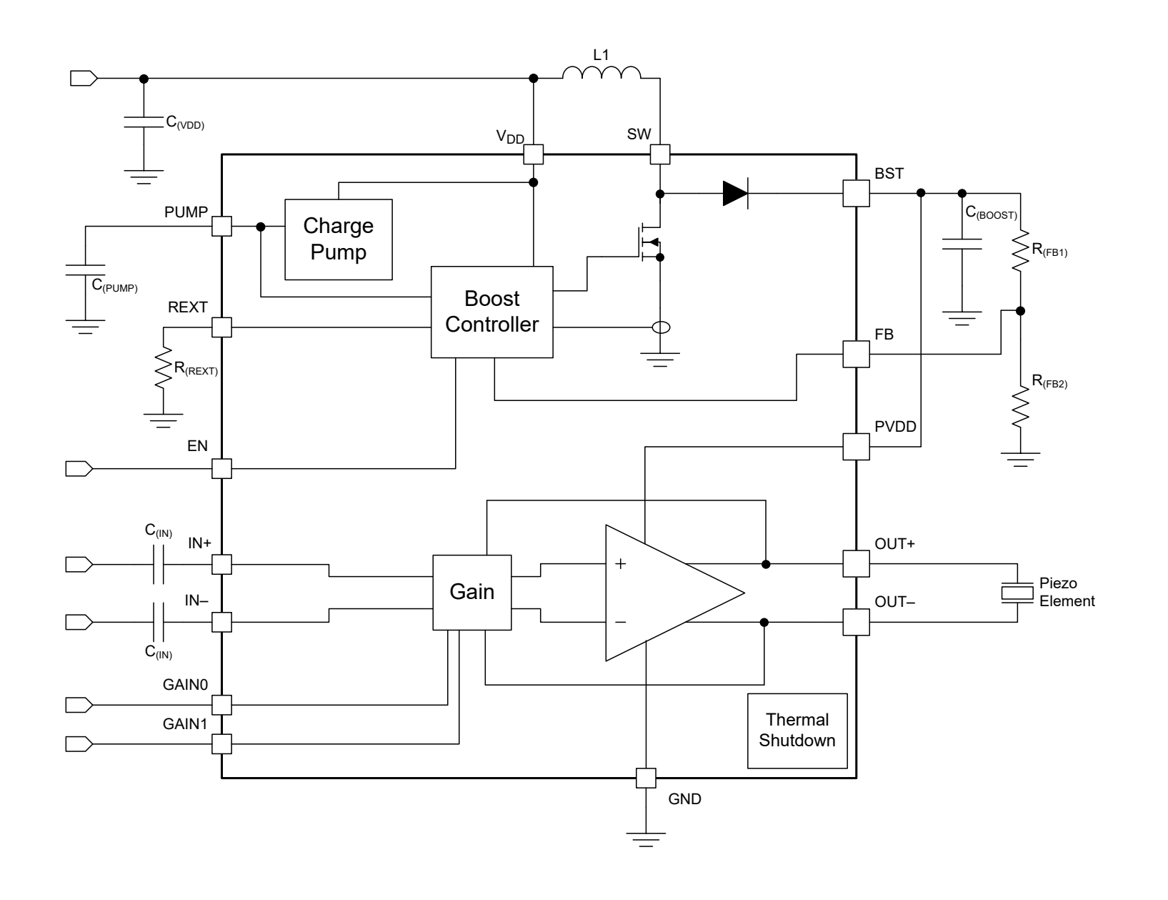
I am trying to use DRV2700 as piezo driver. I built a breadboard-based prototype based on the following schematic (which is from the DRV2700 datasheet). Power input was 5V. The signal (sine wave) inputs (IN+/IN-) were from a signal generator. EN/GAIN0/GAIN1 pins were set HIGH. The measured BST voltage is as expected - 80V. However, the output signal (OUT+/OUT-) was not sine wave (cut off significantly), and it wasn't amplified either... the output signal is also shown below.

I tried 3 DRV2700 chips and they all show the same characteristics. Can anyone help me with this? 

  • Hi, Vincent,

    Welcome to E2E and thank you for your interest in our products!

    Could you provide the external components values that you used in your design? In addition, is the sine wave signal in differential configuration?

    Any other information you could provide will be appreciated.

    Best regards,
    Luis Fernando Rodríguez S.

  • Thanks Luis. Below schematic shows the external component values I used for DRV2700 prototype, basically, I copied it from the DRV2700EMV evaluation board except the REXT resistor (I used 10k instead of 6.04k).

    In terms of sinewave, I used single ended signal, IN- directly connects to GND, IN+ connects to sine signal with 0V off-set voltage. JUST FYI, I also tried output differential (PWM through a external low-pass filter) signal through microcontroller but it show the same issue (no amplification). 

  • Thank you for the details, Vincent,

    When the DRV2700 is in idle state (no input signals), do you see the outputs fixed at ~VBST/2 level?

    Could you also try with a lower resistor (similar to the one used in the EVM)? Usually the output level can be also limited if the resistor is high.

    Do you have details about the FB connection?

    Thank you.

    Best regards,
    Luis Fernando Rodríguez S.

  • Thanks for your quick response Luis.

    I changed the REXT resistor to 6.4k and probed the output signal when there is no input signals. The VBST is 84V while the VOUT+/VOUT- is around 16V with a lot noise. Please see the picture below, the blue signal is one of the VOUT.

    The FB voltage divider is 10k pull-up and 820ohm pull down.


  • Vincent,

    Regarding the analog inputs IN- and IN+, do you have AC-coupling capacitors connected? The analog inputs require of input capacitors in order to correctly reach the common-mode level. I noticed that you mentioned that IN- is directly connected to GND, but this connection is not suggested or the device could have unexpected results.

    Could you try adding 0.1uF capacitors at the input, please? Please let me know how it results.

    Best regards,
    Luis Fernando Rodríguez S.

  • Thanks Luis,

    I tried to added a 0.1uF capacitor on each of the input but it has the same issue, please see picture below. I don't think the AC coupling capacitor matters here since even without input signal, the output voltage is not half of the VBST... something else must be wrong.

    I also attached my prototype below. Do you think breadboard is the issue?

  • Correction: the VOUT+/-  mentioned above is not 16V, it's actually 1.6V (which basically means no output voltage)

  • Hi, Vincent,

    Thank you for the information that you provided.

    Could you provide details about each of the DRV2700 pins voltage level? This would be useful to have a better approach to this issue.

    Thank you.

    Best regards,
    Luis Fernando Rodríguez S.

  • Hi Luis, 

    Thanks for your continuous support. Below is the measure voltage for every pin.

    Pin Voltage (EN=1)
    1 8.0V
    2 5.0V
    3 1.36V
    4 0V
    5 0V
    6 0V
    7 4.8V
    8 4.8V
    9 0V
    10 80V
    11 80V
    12 80V
    13 0.7V
    14 0.7V
    15 1.3V
    16 0V
    17 0V
    18 5V
    19 5V
    20 5V
  • Hi, Vincent,

    Excuse me, are these values the same when you connect the AC-coupling capacitors to the input? Do you see the BST voltage turning off when the EN pin is '0'? If you send a 1V sinewave to the inputs (with AC-coupling capacitors), do you get the same results?

    In addition, have you tried a different unit just to ensure that it is working correctly and it is not related to a device damage?

    Best regards,
    Luis Fernando Rodríguez S.

  • Hi Luis, sorry about the late reply. I missed your response.

    Yes, I got pretty much the same value when connecting a 0.1uF AC coupling capacitor to both inputs.

    When the EN=0, the BST voltage is around 4.8V, so no boosting.

    Yes, I see the same results when sending 1V sinewave with AC-coupling capacitors.

    I tried to solder 3 ICs, and they all show the same issue. So I'm guessing the soldering is ok.

    Thanks

    Vicnent

  • Hi, Vincent,

    One more question, are you connecting the 0.1uF cap to both pins or a 0.1uF cap to IN- and another 0.1uF cap to IN+?  Are you using single-ended or differential signal?

    Best regards,
    Luis Fernando Rodríguez S.

  • Hi Luis,

    Thanks for your help! I connected one 0.1uF to IN- and one 0.1uF to IN+. TBH, I don't think the type of signal or connecting capacitors to the inputs matters here... because I should see a ~1/2 VBST at both of the output pins if there is no input signal, but I didn't see that (what I saw is close to zero output voltage)..

    I think the differential amplifier doesn't function correctly (I tried 3 ICs and all of them showed the same issue)... there could be couple of reasons that I can think of:

    1) the IC got damage during the solder process? can hardly believe this since the silicon should be quite robust.

    2) not sure if it is the noisy breadboard that causes this issue?

    3) do you think I should ground the thermal pad? not sure if that is necessary, but it's hard to do on my hand soldered socket...

    Thanks

    Vincent


  • Hi, Vincent,

    Sorry for my delayed response. For some reason I didn't get your notification in my email inbox.

    Do you have new observations about this issue? Have you tried with your reason number 3 and connect the GND to the thermal pad?

    Please let me know if you have additional questions or comments.

    Best regards,
    Luis Fernando Rodríguez S.

  • Vincent,

    I will close this E2E thread for now. But please feel free to ask for additional support on this thread or start a new one if you have questions about a different topic. We will be glad to support your questions.

    Best regards,
    Luis Fernando Rodríguez S.

  • Hi Luis, thanks so much for your help!