This thread has been locked.

If you have a related question, please click the "Ask a related question" button in the top right corner. The newly created question will be automatically linked to this question.

H bridge instead of DPDT relay?

Other Parts Discussed in Thread: DRV8873, DRV8701, DRV8702-Q1, CSD19538Q2, CSD18543Q3A, CSD88539ND, CSD17581Q5A

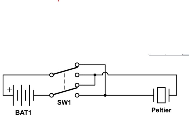
For a new design we want to use a Peltier element (+24V/70W 3.6A max) where we have to switch between cooling and heating depending on the temperature in a small climate  chamber.

Therefore we use a standard LED driver module and a DPDT relay to reverse the current through the Peltier. However for the final design we do not prefer a mechanical relay but switching with MOSFETs (H bridge). So do you have a suitable device for controlling a H bridge where we can reverse the current (like a DPDT switch)? We do not have a microcontroller but we use I2C communication so we can control devices by I2C (by I/O expanders). The bridge must be able to switch at least 4A @+24V.

Best regards

Chris van der Aar

NTS- Group

Eindhoven , The Netherlands

  • Hi Chris,

    The DRV8873H might work, but we would like to understand a little more.

    What is the ambient operating temperature range?

    Can you provide a block diagram of how the H-Bridge would be used?

  • Ok thanks! This device looks very interesting. The ambient temperature range will be max 50C I expect (we don't want to use forced cooling and the PCB will be placed inside a small machine. The Peltier will generate heat but has its own fan so the heat from that part is removed outside the cabinet). The driver on the PCB will be placed outside the climate chamber so the temperature will be rather constant there. The Peltier we want to use is this one: https://www.lairdthermal.com/products/thermoelectric-cooler-assemblies/peltier-power-cool-series/DA-075-24-02/pdf/

    The max current will be 3.7A (4.6A startup current) . The circuit looks similar to the circuit below. In our case the battery is a Meanwell LED driver (+24V/100W) that generates a constant current for the Peltier. The LED driver has an analog dim input that we use for regulating the current (and temperature). The temperature in the climate chamber is measured by an I2C temp sensor and value is readback by a PC that controls the system. So I think we would need the PH/EN input of the DRV8873H to switch the current direction for heating/cooling of the Peltier (we don't need PWM). At this moment we are testing this with a relay but we prefer a semiconductor device for this. I assume that shoot-through of the MOSFET H-bridge  bridge is protected by the device? or do we have to take care for that when switching the PH/EN signal? And can we use the version without SPI? In fact we have SPI on the board so we could use it but this process is controlled by I2C (other devices are I2C) so therefore a little bit unlogical to have SPI for this device but probably we don't need it?

    And do you think we need additional cooling for this device at +24V/3.7A ? Or can we use the GND copper plane of the PCB for cooling. The PCB will be 4 or 6 layer with 1 layer completely filled with GND.

    best regards

    Chris van der Aar

    NTS Systems Development

    Eindhoven The Netherlands

  • Hi Chris,

    The DRV8873 may work, but we need to additional information to be sure.

    Can you confirm how the constant current dimmer works?

    As the current is lowered, does the voltage change?

    If so, what is the lowest voltage at the output?

    The reason for these questions is that VM of the DRV8873 will have to be connected to the output of the LED driver. This could be a problem if the voltage drops below the UVLO voltage of the DRV8873. Also there are a few mA of DRV8873 operating current that may need be taken into account.

    An alternative is to use the DRV8701 or DRV8702-Q1 with external FETs. Doing this allows the VM of the DRV8701 or DRV8702-Q1 to be connected to a different voltage. Some of the protection circuits may need to be disabled, like overcurrent protection.

  • Ok, I will let you know after the weekend because my collegue who is performing measurements at the office for this LED driver is not in here today. So probably he can tell me the voltages he is measuring because the LED drivers and Peltiers are running a life time test where we reverse the current automatically with a mechanical relay.

    The LED driver we are using is  a Meanwell driver:

    https://www.meanwell-web.com/content/files/pdfs/productPdfs/MW/HLG-100H/HLG-100H-spec.pdf

    We control the current by applying a voltage between +1V and +10V at the DIM input. The output current is linear controlled between 10% and 100%. These drivers have some problems with very low currents so therefore it is not possible to regulate the current until 0% but this is not a problem in our application. So at this moment I don't know the voltage at 10% current setting but when it is more then +5V then I assume the DRV8873 would be useful here?

    Regards

    Chris van der Aar

    NTS Systems Development

    Eindhoven, The Netherlands

  • Hi Chris,

    We will await your colleague's findings. Please let us know what you find.

    I did note the following statement on the datasheet of the driver: In the constant current region, the highest voltage at the output of the driver depends on the configuration of the end systems.


    If the voltage at the 10% setting is more than 5V, the device should work.

  • Good morning!

    My colleague did some measurements today regarding the LED driver we are using for controlling our Peltier (and a mechanical relay to reverse the current flow through the Peltier). We are running a life time test where we continuously increase and decrease the current throught the Peltier and at each cycle reverse the current so the Peltier switches between cooling and heating. The Peltier is a +24V/70W type. 

    The results are:

    +21V at 3.5A

    +2.8V at 0.2A

    So with the minimum current this would mean that the undervoltage lockout of the DRV8873 would be active and outputs will be switched off. So I don't know if you have another solution for this? At least it is important that the device can handle 4A or more at +24V and 'break before make' is guaranteed to prevent 'shoot through'of the bridge when reversing the current.

    Best regards


    Chris van der Aar

    NTS Systems Development

    Eindhoven , The Netherlands

  • Additional to the previous answer w.r.t. the UVLO for the DRV8873 I think we would need the DRV8701 or DRV8702 as you earlier suggested. Some questions about this:

    1) According table 9 in the DRV8701 datasheet we would have case 3 when Vbat (bridge voltage) is +2.8V and Vm (driver voltage) is +24V assuming we connect the driver to our fixed +24V. In that case we should disable the high side OCP I understand? I was wondering how the H bridge can still switch in a right way when there is only a few volts over the bridge while the driver operates at +24V?

    2) Which types of MOSFETs would you suggest? We have around 3.6A max current at +24V. For another project in the past I earlier used the T.I. dual N channel MOSFETs for a H bridge of a stepper motor driver https://www.ti.com/lit/ds/symlink/csd88539nd.pdf?ts=1588672207046  but there are of course many others and also types with lower Rdson

    3) What is the difference between DRV8701 and DRV8702 and what would you suggest? In the DRV8702 datasheet I can not find a table for different bridge and driver voltages like the DRV8701?

    4) Can we connect the LED driver 'floating' so the V- of the driver to the low side of the bridge and the V+ to the upper side? The LED driver is an external device and has no relation with our general +24V supply. Or do you think we have to connect the V- of the driver to the GND of our general +24V supply? See block diagram of LED driver below:

  • Hi Chris,

    Chris van der Aar said:
    1) According table 9 in the DRV8701 datasheet we would have case 3 when Vbat (bridge voltage) is +2.8V and Vm (driver voltage) is +24V assuming we connect the driver to our fixed +24V. In that case we should disable the high side OCP I understand? I was wondering how the H bridge can still switch in a right way when there is only a few volts over the bridge while the driver operates at +24V?

    To make the DRV8701 (or DRV8702-Q1) work properly, two supplies should be used at VM. Consider creating a 8V supply from the fixed 24V supply.

    The 8V supply would then be passed through a diode to VM to set a minimum VM voltage.
    The LED driver voltage would also be passed through a diode to VM to create the maximum VM voltage.
    The miminum voltage is needed for operation and the maximum voltage is needed to enhance the high side FET.

    Chris van der Aar said:
    2) Which types of MOSFETs would you suggest? We have around 3.6A max current at +24V. For another project in the past I earlier used the T.I. dual N channel MOSFETs for a H bridge of a stepper motor driver https://www.ti.com/lit/ds/symlink/csd88539nd.pdf?ts=1588672207046  but there are of course many others and also types with lower Rdson

    We will contact the FET team. The choice depends on cost, size, and power losses affecting overall system efficiency.

    Chris van der Aar said:
    3) What is the difference between DRV8701 and DRV8702 and what would you suggest? In the DRV8702 datasheet I can not find a table for different bridge and driver voltages like the DRV8701?

    The DRV8701 and DRV8702-Q1 are very similar. The DRV8701 is an industrial device while the DRV8702-Q1 is automotive. The DRV8702-Q1 has more pins (32 with a 5mmx5mm package), allowing the device to be used in multiple configurations (PWM, PH/EN, or independent half bridge mode). The DRV8701 has fewer pins (24 with a 4mmx4mm package) and two options (DRV8701P - PWM mode and DRV8701E - PH/EN mode) 

    Chris van der Aar said:
    4) Can we connect the LED driver 'floating' so the V- of the driver to the low side of the bridge and the V+ to the upper side? The LED driver is an external device and has no relation with our general +24V supply. Or do you think we have to connect the V- of the driver to the GND of our general +24V supply? See block diagram of LED driver below:

    You will need to connect the V- to the GND of the general +24 supply.  Without this connection, there could be issues with some of the protection features that are GND referenced.

  • Hi Chris,

    I'm the applications engineer for the FET product line. I think the CSD88539ND would work for this application. Keep in mind, that you will need a minimum 6V gate drive since we cannot guarantee rds(on) with VGS < 6V. Worst case conduction loss for 4A: PD = 4A x 4A x 28mOhm x 1.5 (on-resistance tempco) = 0.67W. It will be double, 1.34W, if both FETs are on and conducting the same current. As a rough rule of thumb, the maximum power that can be dissipated in this package is ~2W (see link to technical article below). Alternatively, you could use 2x single, discrete FETs Something like the CSD19538Q2, 100V NFET in 2x2mm SON but your power loss per FET will be about 1.5W and the cost will be higher. In a 3x3mm SON, we have the CSD18543Q3A which is much lower on resistance, can be driven at VGS = 4.5V min but is higher cost than either of the other two solutions. Let me know if you have any questions or need additional information.

    Other Parts Discussed in Post: CSD17581Q5A When starting a new design, engineers are often overwhelmed by the number of package options for power metal-oxide semiconductor field-effect transistors ( MOSFET…

  • Ok thanks for information. I think we will try the solution with DRV8701. We don't use PWM mode. We just want jsimply switch on or off the bridge by TTL level signals from an I2C GPIO expander. This will be controlled by our software. From your answers I understand that we need to connect the +8V supply and the external LED driver supply both to Vm of the chip via diodes so the voltage will vary between +7.5V and +20.5V (assuming a diode voltage drop around 0.5V)? I assume this can be any simple low power diode? Or do you suggest a Schottky here?

    One question about the +8V. I have to make +12V/1,1A for another device (I will use a T.I. DC/DC +12V/2A converter with integrated inductor for that so I have some power left). What do you expect w.r.t. the power consumption from the +8V. Can I use a simple LDO device for that (e.g. from +12V to +8V) . According the datasheet the power consumption of the driver is quite low so I don't expect problems here with that when using a simple low power LDO.

    Best Regards,


    Chris van der Aar

    Sr Hardware Engineer

    NTS -Group Eindhoven , The Netherlands

  • Hi Chris,

    Chris van der Aar said:
    Ok thanks for information. I think we will try the solution with DRV8701. We don't use PWM mode. We just want jsimply switch on or off the bridge by TTL level signals from an I2C GPIO expander. This will be controlled by our software. From your answers I understand that we need to connect the +8V supply and the external LED driver supply both to Vm of the chip via diodes so the voltage will vary between +7.5V and +20.5V (assuming a diode voltage drop around 0.5V)? I assume this can be any simple low power diode? Or do you suggest a Schottky here?

    Yes, a simple low power diode should do the trick. The current should be less than 10mA.

    Using a Schottky would provide a little more low side Vgs if used in series with the 8V supply, and a little more high side Vgs if used in series with the LED driver supply.

    I would recommend using a Schottky in series with the 8V supply.

    Chris van der Aar said:
    One question about the +8V. I have to make +12V/1,1A for another device (I will use a T.I. DC/DC +12V/2A converter with integrated inductor for that so I have some power left). What do you expect w.r.t. the power consumption from the +8V. Can I use a simple LDO device for that (e.g. from +12V to +8V) . According the datasheet the power consumption of the driver is quite low so I don't expect problems here with that when using a simple low power LDO.

    The power should be <100mW. Yes, a simple LDO should work fine.