This thread has been locked.

If you have a related question, please click the "Ask a related question" button in the top right corner. The newly created question will be automatically linked to this question.

DRV10987: DRV10987

Part Number: DRV10987
Other Parts Discussed in Thread: DRV8308, DRV8306, DRV10970, DRV8312, DRV8308EVM

Hi,

We're using DRV10987 to drive NEMA17, 3-phase BLDC motor. Motor MPN: GM42BLF40-128-SJ-126 (gemsmotor  http://gemsmotor.com/nema-17-square-brushless-dc-motor)

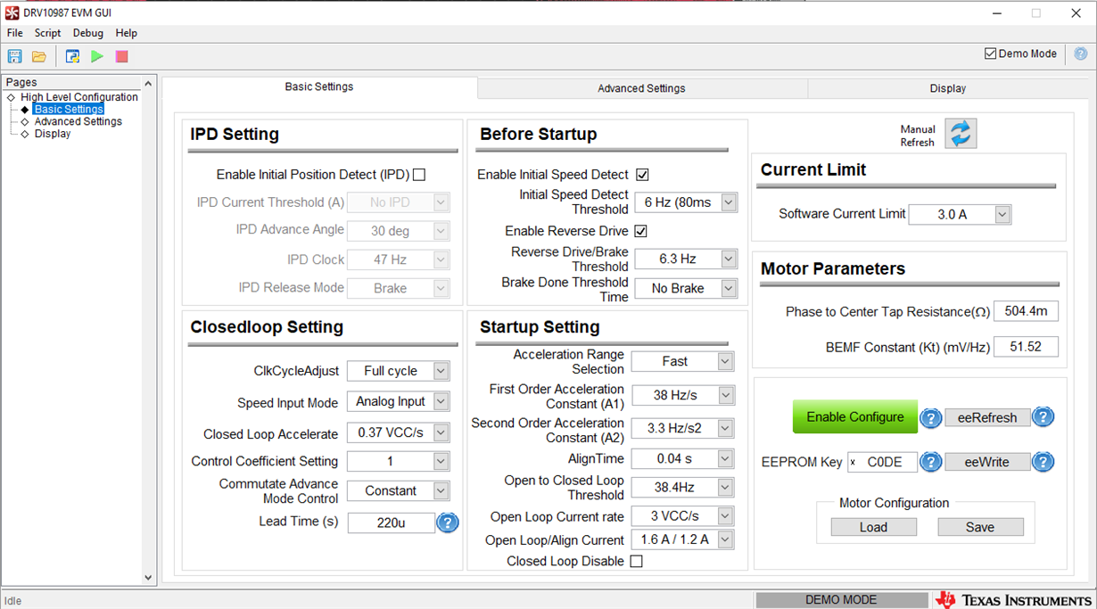
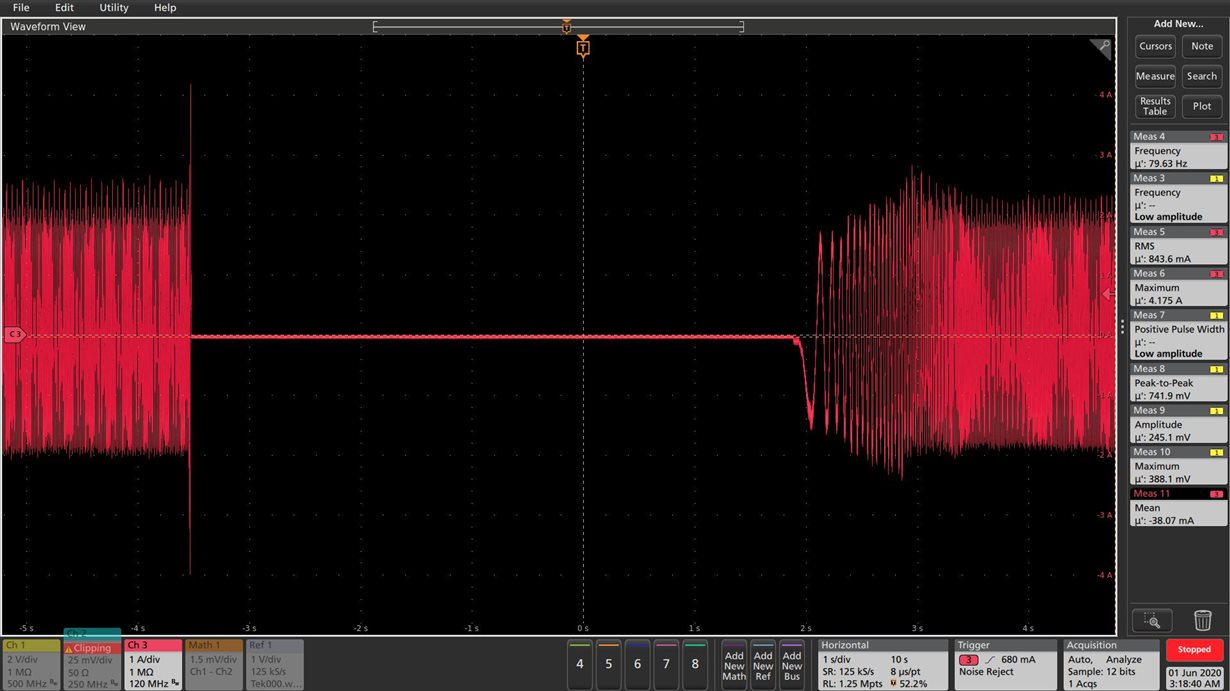
Motor enters into overcurrent protection mode (DRV10987's spec: 3.5A - 4.25A - 5.5A) while running application. This event occurs when there is need of sudden surge in required torque as motor needs to run at back pressure of -5 PSI (application case).  Scope capture attached for phase current on one of phase winding and also, EEPROM configuration file attached 

Questions:

  1. How to avoid overcurrent protection senarios?
  2. Is any acceleration factor is to be changed? any other EEPROM parameter is to be changed?
  3. Any ferrite bead will help in series with motor's UVW terminals

Operating condition:

  • Peak transient current = 3.5A - 4A
  • Average current: 1.5A rms
  • Vcc = 12.56V
  • SPEED voltage : 1.58V
  • Motor speed: Approx. 90-100Hz (as per GUI)
  • Phase to center Tap resistance = 504.4mOhm  (1 ohm/2, Star Winding connection)
  • BEMF constant, Kt = 51.55 mV/Hz
  • Software current limit = 3A
  • Lock detect: current limit check box = OFF, Current Limit for Lock Detection = 3.2A, lock detection control = Range2

I will send some more scope captures tomorrow -

1) VCC voltage and phase current transient rise (zoom scale)

Final_1_30_May.csv

  • Hi Sadashiva,

    Thanks for posting your question in MD forum and thanks for providing all the information. DRV10987 can only support 2-A continuous winding Current and upto 3A during startup and locked condition. 

    1. How to avoid overcurrent protection senarios?

    Looks like your motor is overloading the device. Peak transient current is 3.5A - 4A which is above the device spec of 3A. Do you have control over the surge torque? Reducing the amplitude of surge torque or the rise/fall time of the surge can reduce the current overshoot and avoid overcurrent protection.

    2.  Is any acceleration factor is to be changed? any other EEPROM parameter is to be changed?  

    You can try decreasing the "Closed loop accelerate" in the basic settings tab to the minimum value but there is a high chance that the motor might stall because the motor may not be able to generate the torque demanded by the load due to slow acceleration. Also, disabling the software current limit might help.

    3.  Any ferrite bead will help in series with motor's UVW terminals?

    I don't think ferrite beads would help because I don't see any high-frequency noise issues here. Since your motor has very low resistance, the current drawn by the motor is high. Adding resistors in series to the motor terminals might help limit the current but this will have an impact on the motor speed due to the drop in the phase voltages.

    Regards,

    Vishnu

  • Thanks for response.

    1) We don't have control over the surge torque as BLDC controller board should be retrofit in the existing system. We're just replacing a portion (BLDC controller) of entire system

    2) I have tried with decreasing the "Closed loop accelerate" in the basic settings tab to the minimum value. But, the motor still stall because the motor may not be able to generate the torque demanded by the load

    3) We see some improvement in numbers of motor stall when  software current limit was disabled. But, this one not completely eliminates motor stall

    4) I forgot to mention previously, intent of ferrite bead was to increase series DC resistance in series with motor phase windings since motor is having very low resistance. That will in-turn reduces transient current. Since it has impact on motor speed. 

    Questions:

    1) Which is best alternatives? Requirement: 2A continuous current and 3.5A transient peak current. Vcc= 12.56V, 3-Phase BLDC motor

    I found 2 alternative solution which requires CPU & external transistors.

    https://www.ti.com/product/DRV8306

    https://www.ti.com/product/DRV8308

    2) Whether TI is having System-In-Package providing an integrated solution which performs field oriented control, the 6-step sensorless and other advanced driving algorithms? 

    3) Existing design consists of On Semiconductor's 

    •MC33035-D:  Brushless DC Motor Controller  
    •MC33039:  Closed Loop Brushless Motor Adapter
    Do you have similar solution? a) Closed loop controls using 3 Hall sensor inputs b) Analog voltage input for speed control and c) External motor driver/transistor/FET 4) without external CPU

  • Hi Sadashiva,

    1. DRV8306 and DRV8308 are Gate driver ICs. Selection between the two depends on the wave shape of the BEMF voltage. If the BEMF voltage is sinusoidal, go for DRV8308. If trapezoidal then go for DRV8306. 

    2. We are developing ICs with integrated solutions which can perform algorithms such as FOC and trapezoidal controls. This is still in development and not released to the market yet. 

    3. We have DRV10970 which has integrated controls functionality and Hall inputs but the continuous winding current is only 1A. We don't have any ICs with integrated controls that can support 3.5A transient peak current. All our integrated control devices in DRV10x family support analog voltage input for speed control. 

    I think DRV8312 will be a good bet for you application. DRV8312 is an integrated FET device with external controls. This device can support up to 6.5A.

    Please let me know if you need more information about DRV8x devices. I can redirect you to the techincal experts of these devices. 

    Regards,

    Vishnu 

  • Thanks Vishnu for details.

    1) DRV8306 and DRV8308: How to determine BEMF voltage is sinusoidal or trapezoidal? This needs to be tested with BLDC Motor along with associated pump assembly? 

    2) I'm not finding firmware source code for controller, MSP430G2553IPW20 that was used in DRV8308EVM in product page. Can you please share CCS project container along with source code?

    3)TI having 3-phase BLDC controller solution which meets all the following 5 requirements a) Closed loop controls using 3 Hall sensor inputs or sensorless b) Analog voltage input for speed control and c) external FET or internal FET d) without external CPU (ex., for PWM generation) e) continuous current 1.5A rms and peak transient current 4A max.

    4)TI having 3-phase BLDC controller solution which meets all the following 4 requirements a) Closed loop controls using 3 Hall sensor inputs or sensorless b) 1-PWM input for speed control and c) external FET or internal FET  d) continuous current 1.5A rms and peak transient current 4A max.

    DRV8312 meets either above item #3 or item #4 ?

  • Sadashiva,

    1. Your motor datasheet will list this information or you can measure it yourself. Please check section "2.3 Motor Velocity Constant" of the following tuning guide: http://www.ti.com/lit/ug/slou395d/slou395d.pdf?ts=1591284208976
    2. Firmware is in this post: https://e2e.ti.com/support/motor-drivers/f/38/p/787557/2912142?tisearch=e2e-quicksearch&keymatch=drv8308%20firmware#2912142
    3. These DRV8308 and DRV8306 are the closest we have to fufilling your requirements but they require an MCU for configuration. Many of the settings can be burned into an external EEPROM or the internal OTP so you may be able to operate without an MCU after initially programming the device in production.

    Regards,

    -Adam

  • Thanks Adam for above details..!

    Adam, Vishnu,

    Let me know if you have further comments on item #3 & item #4 mentioned in my previous query (Jun 4, 2020 11:36 AM) -

    I want to make sure that we selected best available solution from TI.