This thread has been locked.

If you have a related question, please click the "Ask a related question" button in the top right corner. The newly created question will be automatically linked to this question.

BOOSTXL-DRV8320RS: Current Control Signals

Part Number: BOOSTXL-DRV8320RS
Other Parts Discussed in Thread: C2000WARE, DRV8301, MOTORWARE

Hey TI - I am hoping you can help me understand the current control signals.

I am running the LAUNCHXL-280049C development board with the BOOSTXL-DRV8320RS inverter.  I am using C2000Ware_MotorControl SDK 3.00.01.00 on CCS V9.3.0.00012.

I am driving a small 3phase, BLDC blower (MOOG BSB19-16BN-04CS) and am currently experimenting with lab 7 (is07_speed_control).  I have not modified the code and am using motor parameters generated in lab 5. The inertia value was provided by Moog.

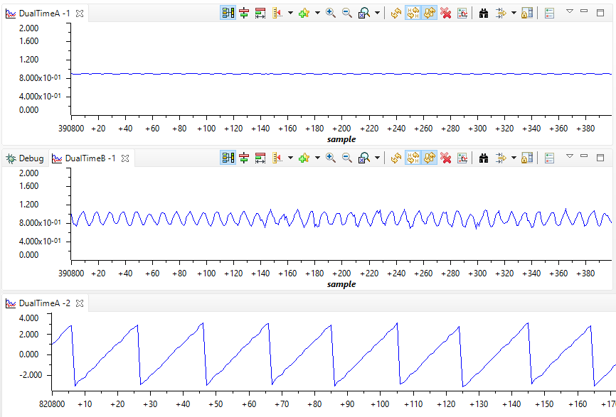
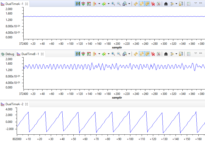
I am using the datalog to capture Idq_ref_A.value[1] (Iq_ref) and Idq_in_A.value[1] (Iq_in).  And am graphing both.

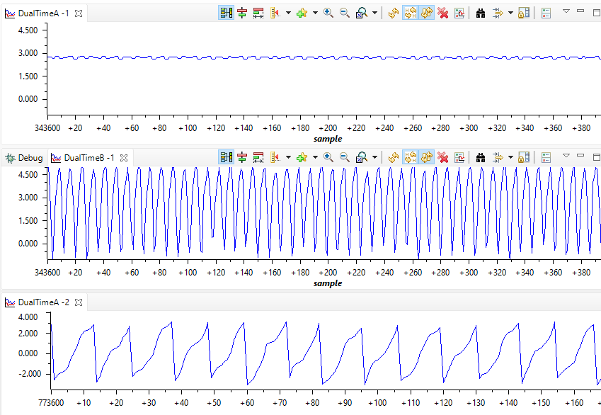
OK.  So everything works fine up to 400Hz on the speed reference.  And by fine I mean both Iq_ref and Iq_in are both stable and Iq_in tracks to Iq_ref. But once I get above some threshold value of speed reference (450Hz in this case), Iq_ref goes to ~ 2.7A and seems stable while Iq_in starts oscillating from just under 0 A to almost 5A. See screen shot below where Iq_ref is on DualTimeA and Iq_in is on DualTimeB.

My power supply reads 24V, 1A so I know it is not limiting, etc.

I could understand if Iq_ref started oscillating (indicating a control problem) but not Iq_in.

As a side note - Iq_in oscillates if I use the Park transform to calculate Iq_in or if I use the estimator to get Iq_in.

Any thoughts on why this is happening?

Thanks!

Brett 

  • Sorry - forgot the screen shot.

    This first one show Iq_ref, Iq_in, and estOutputData.angle_rad when the blower has reference speed setting of 300Hz.

    This next screen shot  shows the same except the speed reference is 400Hz.

    And finally, this last shot shows the same 3 waveforms when the commanded speed is 500Hz.

    Any thoughts on why Iq_in went out of control?

    The angle seems severely distorted when Iq_in goes out of control.  Interestingly, the shift from stable to unstable seems to be very abrupt.  In this case, Iq_in is stable at 465 Hz and unstable at 475Hz.   Any reason why the angle is getting distorted so bad? 

    Thanks for your help!

    Brett


  • Check if the maximum current and bus voltage is enough for such high speed. You may try to increase both to see what happens.

  • Mr Luo - I thought that at first so I switched from 12V, 10A to 24V, 20A power supply and see the same response.  Is and Vs are not maxing out when this occurs.  And actually I can command higher speeds and the blower/drive responds.  I just don't understand why the input current would seem to go unstable while the command current is stable.  Does that make sense to you?  And why the angle gets distorted? 

    I did more testing this weekend.  I put the same motor on the F28069M LaunchPad with the DRV8301 BOOSTXL inverter.  On this setup, I did not see the instability.  I was able to drive to ~ 55krpm without issue.  Angle stayed good and Iq_in stayed good.

    I then went back to the F280049C with the DRV8320RS and repeated what I was seeing last weekend.

    Are you seeing similar issues when others switch from MotorWare to C2000 MotorControl?  Any thoughts on how to overcome this problem?

    Thx

    Brett

  • I didn't find such issues during test the labs in MotorControlSDK. Did you fine-tune the speed controller for the motor? The current sensing circuits are different between these two kits.

    Could you please post the user.h and capture some current waveforms with an oscilloscope if you still have any questions?

  • OK.  I figured it out.

    The issue ends up being tied to my PI gains.  Interesting how the PI gains affect the estimator output.  Any thoughts on why?

    Anyway, it turns out the default PI gain calculation is incorrect.  

    Findings:

    1. The default BWc_rps parameter is defined to be 100 * 2 * pi. This really should be(1/currentCtrlPeriod)*2*pi/b where b is a design factor.  TI set b = 4 in the Motorware equations (e.g., pg 102 in Instaspin Lab User Guide).   Changing BWc_rps will allow the default Kp_current term to calculate correctly.

    2. I am not sure why BWc_rps is also used in the Kp_speed and Ki_speed calculations.  I think you should use the pole closest to the 0dB crossing...and that would be the LPF pole (USER_SPEED_POLE_rps).

    3. Finally, there is an extra 2*pi in the Kp_speed gain calculation.  Not sure why.

    Making these changes sets the default gains as follows:

    Speed Controller:

    Kp_speed = USER_SPEED_POLE_rps/BWDelta/Kctrl_Wb_p_kgm2

    Ki_speed = USER_SPEED_POLE_rps*speedCtrlPeriod_sec/BWDelta/BWDelta

    Current Controller:

    Kp_current = BWC_rps*Ls = 2*pi*(1/currentCtrlPeriod)*Ls/4

    Ki_current = (Rs/Ls)*currentCtrlPeriod

    Note - with these values, the zero (Ki_speed) is set BWDelta to the left of the 0 dB crossing and the LPF pole is set BWDelta to the right of the 0 dB crossing.  And the current controller pole is set way to the right of the LPF pole.

    These got me close. 

    I then used the torque control lab to set Kp_current.  I ended up changing the 4 to a 10.

    I then used the speed control lab to confirm all worked well.

    Cheers!

    Brett