This thread has been locked.
If you have a related question, please click the "Ask a related question" button in the top right corner. The newly created question will be automatically linked to this question.
Hi user6376435,
The DRV8412 may not be the best device to use.
1) Did you regulate the current using VREF? If so, there is no VREF equivalent. External circuitry is required.
2) The logic table is not the same. If PWMA is connected to /RESET_AB and /RESET_CD, the outputs will transition from drive to Hi-Z. This is different than the TB67H400A.
As possible alternatives, please consider devices like the DRV8704 (brushed motor) or DRV8711 (stepper or brushed motor) with external FETs? These devices can regulate current automatically and have a PWM mode. A SPI interface is available to program the current regulation.
Answers to your DRV8412 questions:
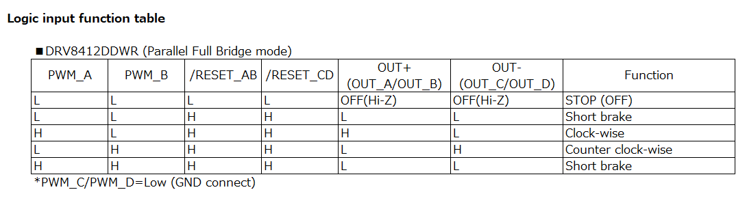
I think that I can control the output by how to use that is approximately equal to a current motor driver if I use "Parallel Full Bridge Mode" of DRV8412, how about?
Yes, this should provide approximately equal to current motor driver.
Is there in particular the problem about the connection of /RESET signal and the PWM signal? [TB67H400A] [DRV8412] INA1 => PWM_A INA2 => PWM_B PWMA => /RESET_AB & /RESET_CD
There are no issues. But the operation may not be the same.
If you want to match the operation, please provide the exact sequences used in the existing system. We will work with you to match them.
Hi Rick
Thank you for an answer.
Q:Did you regulate the current using VREF?
A:I do not set a limit to an electric current that I use VREF.
Q:The logic table is not the same.
A:I recognize that the control logic has to change it.
(Attachment: DRV8412 circuit under consideration)
I would like to confirm about the proposed "DRV8704" and "DRV8711".
Regards.
Hi user6376435,
The DRV8412 could be used as potential replacement, but it appears the connection to TB67H400A may need to be routed to both the PWM_A and PWM_B of the DRV8412. The signal may also need to be gated to allow it to pass when PWM'ing and to set the output low when not PWM'ing.
What would you like to confirm about the DRV8704 and DRV8711?
Hi Rick
Q:What would you like to confirm about the DRV8704 and DRV8711
A:I have confirmed the data sheets for two types of devices, but I think that DRV8412 has less modification, so I would like to proceed with the study with DRV8412.
How about the relation of PWM/RESET/OUT signal with the contents of the attached file?
Best Regards,
Toshiyuki Yoshizawa
Hi Yoshizawa-san,
Please note the last line in the Logic Input Function table is not correct.
For the case PWM_A = PWM_B = /RESET_AB = /RESET_CD = H, OUT_A/OUT_B and OUT_C/OUT_D are both H
Also, please note 100% duty cycle is not available in the DRV8412. This is due to the need to refresh the boost capacitor.
What is the target PWM frequency?
Please let us know if you have further questions.
Hi Rick
The logical table was wrong.
Excuse me. Both outputs will be H.
We understand that 100% is not available.
Currently, I was operating at PWM=20kHz cycle,
If there is no problem this time, I am thinking at 20 KHz.
Thank you for your response.
There are no additional confirmation items.
Best Regards,
Toshiyuki Yoshizawa
Hi Yoshizawa-san,
Please note C284 and C413 should be 1.0uF in the pdf file.
There is no problem operating at 20kHz.