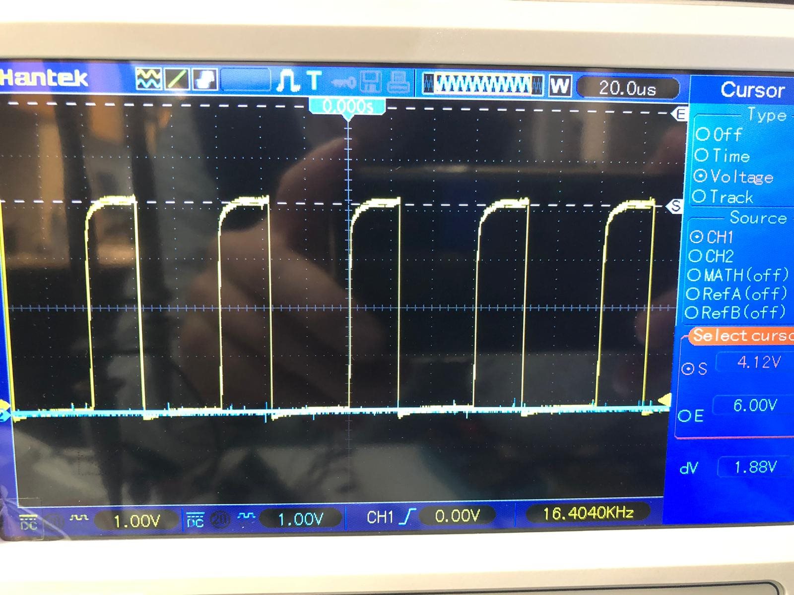
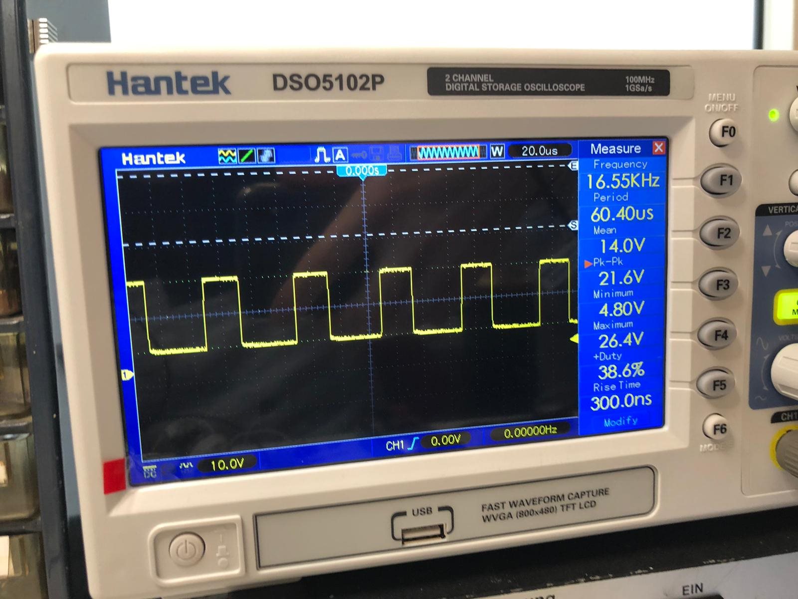
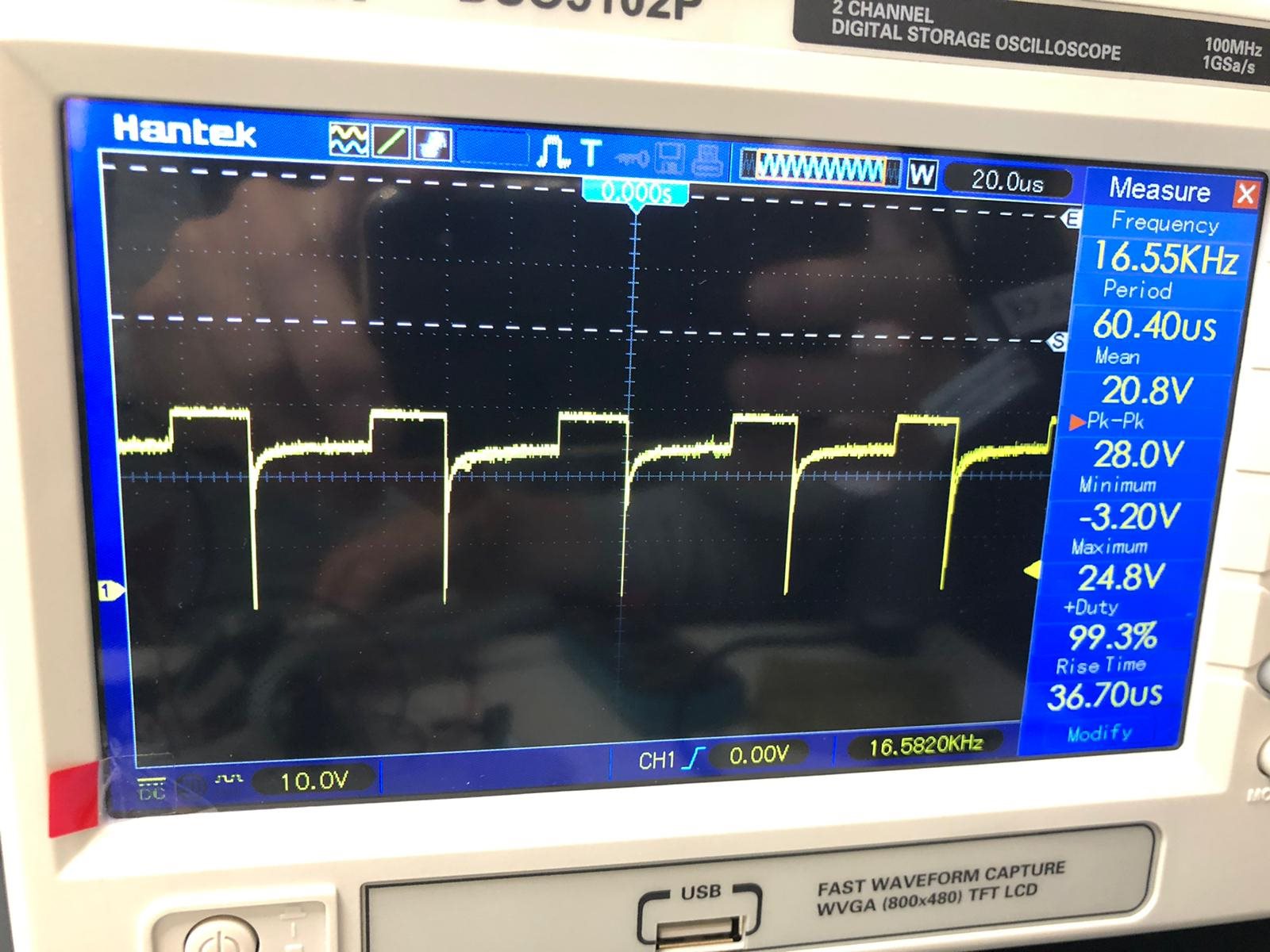
We have an issue with the DRV8871. We input a PWM signal as can be seen in image 1. This shows the inputs to both in1 and in2, one is our PWM input signal and the other is ground. But then when we measure out1 we see something strange as can be seen in image 2. The out1 pin gives a PWM signal which doesn't go all the way to 0, the minimum is ~5V. Then when we connect the brushed motor we get a distorted PWM signal as can be seen in the last image. Also notice that without the motor connected the mean voltage is 14V, but when the motor is connected it suddenly rises to 20.8V.
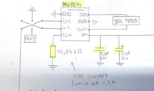
The input PWM doesn't change when the motor is attached so the problem seems to be in the chip. The schematic below shows the values of the caps and resistor we use. It also shows the DPDT switch that we use to change the direction in which the motor spins.
SCHEMATIC:


