This thread has been locked.

If you have a related question, please click the "Ask a related question" button in the top right corner. The newly created question will be automatically linked to this question.

DRV8301: shutdown after power up

Part Number: DRV8301

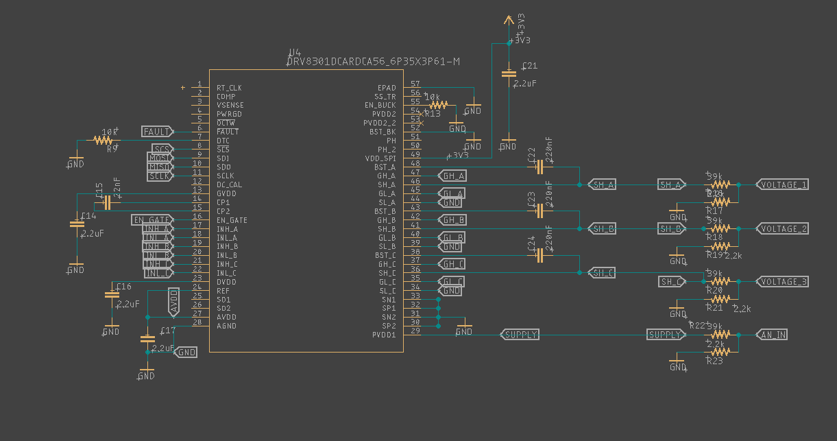
I am trying to debug a fault that keeps occuring with the drv8301. After powering up the device with 16V I see excellent voltages for GVDD, AVDD, and DVDD. Also I am able to read the spi registers.

GVDD = 11.5V
AVDD = 6.3V
DVDD = 3.3V

However after about a minute the drv8301 appears to shut down and the voltages all drop to 0. The input voltage remains the same 16V. The spi registers all read 0xffff. How can I debug this? I am not even driving a motor. Just applying power to the drv8301. Also I don't use the built in Buck so I have bst_bk connected to gnd and en_buck pulled to gnd. What could causing this shutdown? What other debugging can I do to find the problem? I have the problem with 8 boards.

  • Hi Drey,

    Thanks for posting to the MD forum!

    Are you able to read any SPI bits in Status Register 1 or 2 before nFAULT goes low? Is there an external resistor pullup on nFAULT?

  • Thank you for the reply!!

    I do have a pull up on nfault but I have also tried it without a pull-up. I am using the open source VESC hardware design which should be pretty fool proof. When I use the Vesc software to read the spi registers they always come back 0x7800 for all the registers. Then when it goes in to fault condition they are all 0xffff. Should I replace the pull up on the nfault line?

  • Hi Drey,

    Sorry for the late response! I just now saw your reply and will look over it and reply later this afternoon.

    Regards,

    Anthony Lodi

  • Hi Drey,

    Could you plot the SCS, MOSI, MISO, and CLK pins using an oscilloscope while performing a SPI read command, both before and after the DRV8301 shuts down? I want to make sure that there is not an issue with the SPI commands being delivered to the DRV8301. If you don't have a 4 channel oscilloscope you can plot MOSI, MISO, and SCS pins separately, each showing the CLK signal in each plot. If we can properly access the registers then it will be easier to find out the reason nFAULT is reporting an error.

    Regards,

    Anthony Lodi