This thread has been locked.

If you have a related question, please click the "Ask a related question" button in the top right corner. The newly created question will be automatically linked to this question.

DRV10987EVM: Two questions about the use of drv10987EVM

Part Number: DRV10987EVM
Other Parts Discussed in Thread: DRV10987, MSP430G2553, DRV10983-Q1

Dear technical engineer, I am a FAE Intern of Ti. In the process of using drv10987evm, there are two questions:, I hope to consult the corresponding engineers。

Question 1:Difference between "FOC" and "sinusoidal control" in operation efficiency and noise of BLDC motor.

Question 2:The reason of serious phase current harmonic when "open-loop to closed-loop switching frequency" is low.

About Question 1:

Taking drv10987 as an example, BLDC motor driver chip belongs to sinusoidal control. Now another common control method of BLDC motor is FOC. At present, we hope to understand the difference between FOC and sinusoidal control (taking drv10987 as an example) in the operation efficiency, noise level, torque ripple and dynamic response speed of BLDC motor. Our current application goals are simple BLDC motor applications such as fans and air purifiers. We need to explain the performance differences between FOC and sinusoidal control in BLDC motor drive to give customers a more objective application evaluation.

About Question 2:

First of all, I will briefly explain my experiment:

Motor RPH_CT=0.4Ω,Kt=63.568mV/Hz,4000RPM,24VDC,polar logarithm=8。

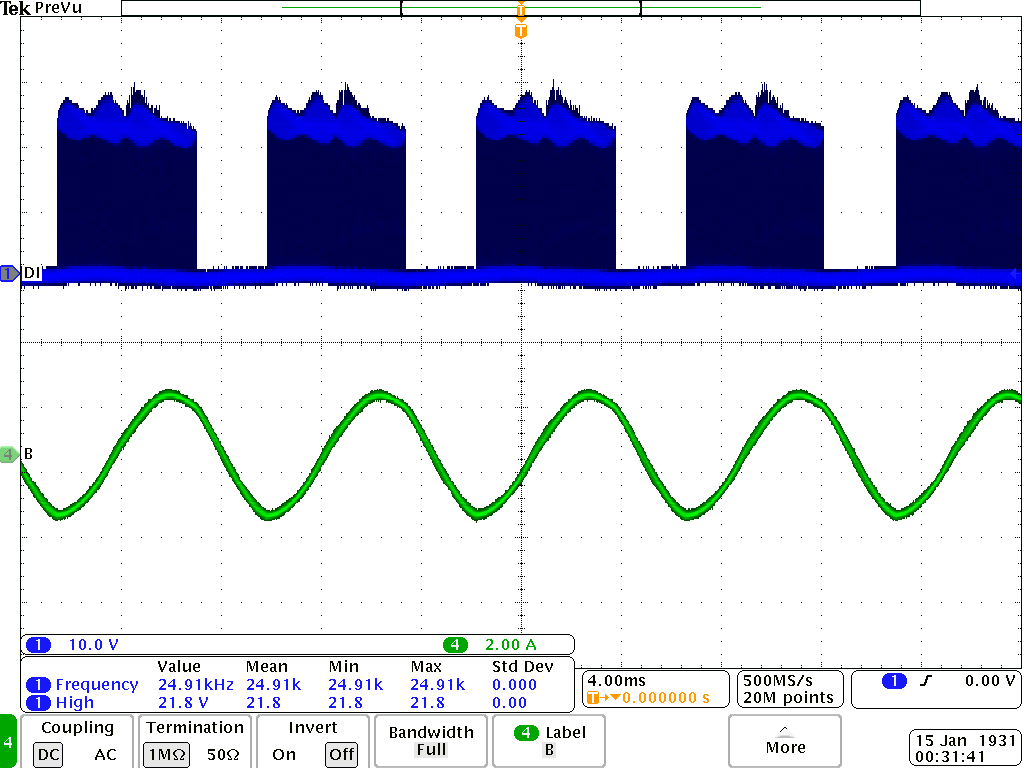
According to the setting suggestion in Drv10987 Tuning Guide document, the open to closed loop threshold should be selected as one third to one fifth of the maximum motor speed, in this case, it is 106hz-177hz. Therefore, the setting value of open to closed loop threshold in this example is 128Hz. The experimental results are consistent with the description in the document. The waveforms of phase current and phase voltage are shown in the figure below.

In practical applications, customers may also want to try a lower threshold so that the motor can ramp faster from zero to full speed. This is because the motor accelerates faster in a closed loop. When we set the switching threshold to less than one fifth of the maximum speed, and we observe the waveform of the phase current. Now let's take specific examples:

We set the open to closed loop threshold to 12.8hz, 25.6hz, 38.4hz, 64Hz, 76.8hz and 128Hz.When the threshold value of threshold is reduced, the harmonic in phase current will be more serious. At the same time, the switching failure from open-loop to closed-loop may occur when the threshold value is low. This is mainly because the equipment triggers the current protection due to the sudden increase of current during the switching process. Here we do not want to argue about the harm of low threshold, but try to analyze why low threshold will lead to current waveform distortion in open-loop state, and also want to understand why it is easier for equipment to switch to closed-loop state unsuccessfully in this case.

The above is my question, thank you for your reading, welcome to exchange.


  • Hi Dong,

    Thanks for posting your question in MD forum.

    FOC Vs 180⁰ Sinusoidal Control

    Performance wise, the major difference between FOC and Sinusoidal control will be the speed and torque regulation in dynamic conditions. In FOC the speed and torque are controlled independently so the torque and speed regulation are good even in dynamic conditions. In Sinusoidal control, commutation is based on the estimated BEMF constant and there is no feedback loop to regulate speed and torque. So the speed and torque regulation in dynamic conditions will be poor in sinusoidal control. We can keep stating more differences but if you could provide the actual application then it will be easy for us to discuss.

    Question 2: Open to closed loop threshold frequency

    Choosing the Open to closed loop threshold frequency depends on the maximum motor speed (electrical frequency) and more importantly, the BEMF constant Kt. In open loop operation, device estimates the BEMF constant Kt. Motor should be able to generate sufficient BEMF for the device to accurately estimate Kt within the chosen open to closed loop threshold frequency. If the Kt of the motor is high (>100 mV/Hz), then the motor can generate sufficient BEMF voltage even at lower frequencies so we can choose a lower open to closed loop threshold frequency. However, if Kt is too low (<10 mV/Hz), then the open to closed loop threshold frequency should be high so that the motor will be able to generate sufficient BEMF voltage for the device to sense and estimate Kt. While transitioning from open to closed loop, if the estimated Kt is not within the defined Abnormal Kt lock detect threshold, the device will trigger Abnormal Kt fault. This is the fault that you are seeing at lower open to closed loop threshold frequencies. Reason for the distortion in current waveform at lower open to closed loop threshold frequencies is because of wrong Kt estimation.

    Regards,

    Vishnu


  • Hi Vishnu

    Thanks for your comments. My name is Gabriel, Dong's mentor. 

    What we are targeting is living a fan and similar applications like air-purifier. 

    Customer major requirement included:

    1. Stable air-flow. (That will require speed close loop control but don't need very accurate closed-loop performance)
    2. Good noise and vibration performance during startup and normal operation

    As FOC could directly control the output torque, the response performance definitely will better than sine wave control.

    But living fan's load (torque) won't significantly change during normal operation, so I am not sure will this advantage could bring more value to customers besides improved response time. Especially for noise and vibration performance, are FOC will achieve much better performance in this field?

  • Hi Gabriel,

    Thanks for the details.

    As you rightly mentioned, for fan applications, the load will not change dynamically. Sinusoidal control with external speed loop should be able to provide stable air flow but if the application demands better speed regulation then FOC will be the way to go. We have a reference design using DRV10983-Q1 motor driver and MSP430G2553 (MCU) for speed control. This design specifically targets small motor modules, particularly fans.

    In general, torque ripple in FOC is lower than Sine control and the noise and vibration is also better compared to Sine control. However, for fan applications, I think noise and vibration performance that sine control provides should be sufficient as the sine control operates based on 180 deg commutation.

    Regards,

    Vishnu 

  • Vishnu

    Totally agree with you. Another question is we found the current distortion with sine wave control during low rotation speed (Like diagram Dong have shown in previous threads marked as 12.8Hz).

    I wonder to know are such a phenomenon is normal or not? What's the root cause of such a phenomenon?

    The second thing I want to know is the meaning of commutation advance time control. Is it the similar as FOC control D-Q conversion>?

  • Hi Gabriel,

    Are the waveforms shown at different open to closed loop threshold frequency captured when the device was in open loop or in closed loop? I'm assuming this is in closed loop because it is normal to see current distortion when the open to closed loop frequency is set low because in open loop the device estimates BEMF constant Kt. For low Kt motors, the open to closed loop threshold frequency should be set high for the motor to generate sufficient BEMF voltage and the device to estimate Kt. When open to closed loop frequency is set low and if the current waveform in closed loop is distorted then the Kt estimated by the device in open loop may not be accurate. Device commutates based on the zero crossing information derived from the estimated Kt. Wrong Kt estimation leads to incorrect zero crossing and causes current distortion. 

    Commutation advance time control is used to improve the efficiency of the device and motor. This parameter controls the phase difference between the phase current and the BEMF voltage. Maximum efficiency is achieved when the phase current is aligned with BEMF voltage. At this condition, the ratio between current drawn from the power supply (Icc) and the motor speed will be minimum and the angle between rotor flux and stator current will be 90 deg(optimum efficiency). This is very similar to setting Id=0 in FOC for non-salient permanent magnet motors.   

    Regards,

    Vishnu