This thread has been locked.

If you have a related question, please click the "Ask a related question" button in the top right corner. The newly created question will be automatically linked to this question.

BOOSTXL-DRV8320RS: Adjusting voltage divider for current and voltage sense for 12 volt low power sensorless BLDC

Part Number: BOOSTXL-DRV8320RS

Hello,

We are using the BOOSTXL-DRV8320RS and TMS320F28004x with a very small low power motor, roughly 1.8 watts.  The motor voltage is 12V and draws roughly 0.15 amps @ 4000 rpm.  Max motor current is 0.620 amps.

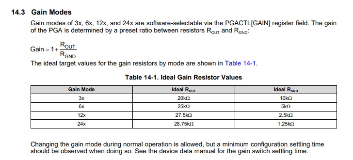
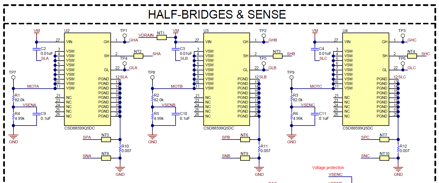
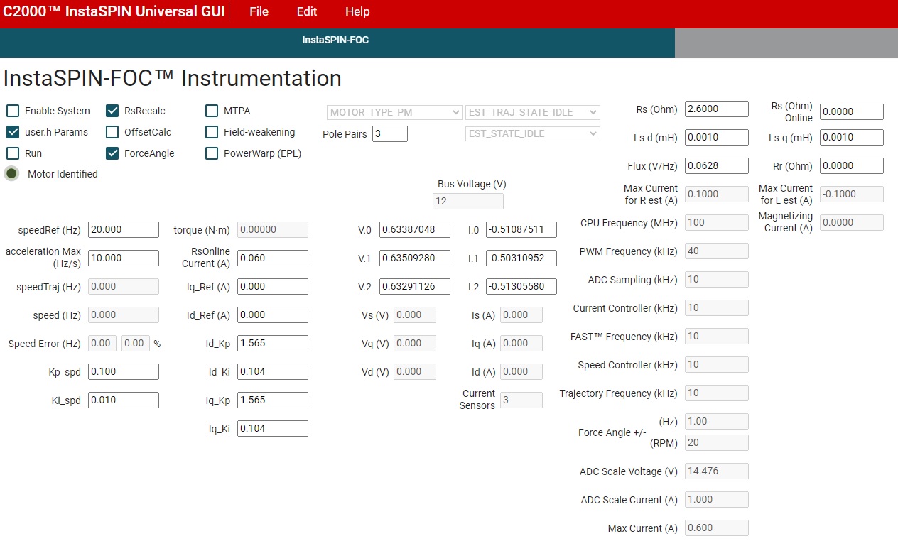
I see that we can adjust the current sense from default 12 to 24 with the PGA but with the recommended resistor values the full scale is still much to high.  Are we able to user a gain/voltage diver to decrease full scale and increase resolution then adjust USER_ADC_FULL_SCALE_CURRENT_A from user.h?  What is a good rule of thumb for head room?  Should we also adjust the cap values?  Is there an advantage of using one gain over another?

We also have the same question for the voltage sense?  If we adjust the voltage divider, R1/R4, R2/R5, and R3/R6 do we only need to adjust USER_ADC_FULL_SCALE_VOLTAGE_V in user.h?  How much heaqd room should we allow? Should we also adjust the cap values?

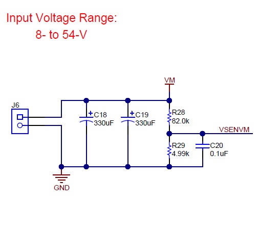
I assume we do the same for VM with R28/R29 as the others above?

Thanks in advance!

  • Sorry for the poor formatting above, but I have included the reference images below:

  • You might change the shunt resistors (R10, R11, R12) for current sensing since the rated current of your motor is very small. And change dividing resistors (R1, R2, R3) for voltage sensing. You don't need to change other components on the BoosterPack board, but you should set the correct scale value of current and voltage accordingly in the file of user.h in the lab project if you changed these resistors in the sensing circuit.  

  • Thank you Yanming!

    1. For voltage sense, I plan on changing R1, R2, R3 values from 82k to 16.9k to get a full scale value of 14.476 ~ 20% head room (12V).  Do we need to do the same thing for R28 for VSENVM?
    2. With the above resistor change, the voltage filter pole is now 414.25Hz.  I know the documentation recommends for this value to be between 200 and 400.  Is there an optimal value we should target?

  • After adjusting the our 4 voltage and 3 current sense resistors along with associated user.h params (listed below), we are unable to have the motor identified light go green in the GUI and therefore are unable to click the run box.

    While running Lab02 in debugger we noticed that motorVars.Vbus_sf ~ 6V even though we are supplying 12V.

    We have replaced the foloowing resistors:

    • R1, R2, R3, and R28 with 16.9k
    • R10, R11, and R12 with 0.3

    Adjusted the following:

    • #define USER_NOMINAL_DC_BUS_VOLTAGE_V ((float32_t)(12.0))
    • #define USER_ADC_FULL_SCALE_VOLTAGE_V ((float32_t)(14.476))
    • #define USER_ADC_FULL_SCALE_CURRENT_A ((float32_t)(1.000))
    • #define USER_VOLTAGE_FILTER_POLE_Hz ((float32_t)(414.25))

    // the defines
    #define BOOSTX_to_J1_J2     0
    #define BOOSTX_to_J5_J6     1
    
    #define BOOST_to_LPD        BOOSTX_to_J1_J2
    //#define BOOST_to_LPD        BOOSTX_to_J5_J6
    
    //! \brief Defines the nominal DC bus voltage, V
    //!
    #define USER_NOMINAL_DC_BUS_VOLTAGE_V         ((float32_t)(12.0))
    
    
    //! \brief Defines the maximum voltage at the AD converter
    //!        full scale voltage of AD converter
    //#define USER_ADC_FULL_SCALE_VOLTAGE_V         ((float32_t)(57.528))
    #define USER_ADC_FULL_SCALE_VOLTAGE_V         ((float32_t)(14.476))  //Chage R1, R2, R3, R28 from 82.0K --> 16.9K


    //! \brief Defines the maximum current at the AD converter
    //!        BOARD_BSXL8320RS_REVA, Gain=12
    //#define USER_ADC_FULL_SCALE_CURRENT_A         ((float32_t)(42.843))
    //BOARD_BSXL8320RS_REVA, Gain=12
    //#define USER_ADC_FULL_SCALE_CURRENT_A         ((float32_t)(0.750))  //Change Shunt Ressitors R10, R11, R12 from 0.007 --> 0.4
    #define USER_ADC_FULL_SCALE_CURRENT_A         ((float32_t)(1.000))  //Change Shunt Ressitors R10, R11, R12 from 0.007 --> 0.3
    
    //! \brief Defines the analog voltage filter pole location, Hz
    //!
    #define USER_VOLTAGE_FILTER_POLE_Hz           ((float32_t)(414.25))
    
    
    //! \brief ADC current offsets for A, B, and C phases
    //#define IA_OFFSET_A    (-21.87679670)        // ~=0.5*USER_ADC_FULL_SCALE_CURRENT_A
    //#define IB_OFFSET_A    (-21.57054520)        // ~=0.5*USER_ADC_FULL_SCALE_CURRENT_A
    //#define IC_OFFSET_A    (-21.98300740)        // ~=0.5*USER_ADC_FULL_SCALE_CURRENT_A
    
    #define IA_OFFSET_A    (-0.51097733)        // ~=0.5*USER_ADC_FULL_SCALE_CURRENT_A
    #define IB_OFFSET_A    (-0.50316352)        // ~=0.5*USER_ADC_FULL_SCALE_CURRENT_A
    #define IC_OFFSET_A    (-0.51292282)        // ~=0.5*USER_ADC_FULL_SCALE_CURRENT_A
    
    
    //! \brief ADC voltage offsets for A, B, and C phases
    #define VA_OFFSET_V    (0.74183482)    // ~=1.0
    #define VB_OFFSET_V    (0.74324220)    // ~=1.0
    #define VC_OFFSET_V    (0.74093384)    // ~=1.0


  • You might use CCS to open and debug the related lab project since you changed the hardware, which should be easy to do.

    You need to check the "Enable System" first and then check the "Run".