This thread has been locked.

If you have a related question, please click the "Ask a related question" button in the top right corner. The newly created question will be automatically linked to this question.

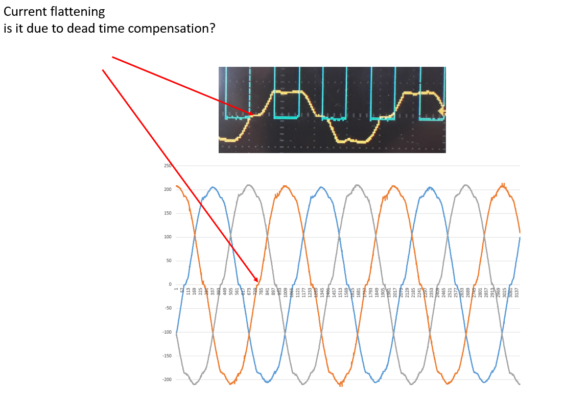
DRV8353R: Current Waveform Flattens due to ?

Part Number: DRV8353R
Other Parts Discussed in Thread: DRV8302, DRV8353

Hi all,

I am using DRV8353 and DRV8302. Today I realised that my motor output currents are flattening when they are passing through zero amps. I am using the same firmware in other controller that do not use these ICs.

From previous experience I faced the same issue when I was using dead time compensation. This time I do not.

Could you let me know if the above ICs are using this concept?

If not, do you have any other idea about why this is happening? 

If you need any more information please let me know.

Thank you very much for your help,

Nick

  • Nikolaos,

    Thanks for posting on the MD forum!

    Yes this would seem to be deadtime or similar. Could you post a screenshot including the phase current and both high side gate as well as low side gate of the same phase?

    Regards,

    -Adam

  • I do not think that it is just dead time insertion, but mostly dead time compensation. So it seems to me that the driver adds or substracts dead time from the TOP PWM according to the current level.

    This leads to the current distortion.

    I have tried with different dead time (250ns or 1us) but the issue is there.

    I will take the measurements and come back to you.

    Thanks a lot.

  • Hi guys,

    So yellow is the motor phase  current, red is the bottom mosfet pwm and light blue is the top mosfet pwm.

    Please notice that top pwm is measured with differential probe, do not mention any differences in voltage levels.

    I cannot see anything strange but I do not think that this can be just visible.

    Thank you very much for your help,

    Nick

  • Any idea about this waveform, can you let me know if this driver IC is compensating for dead time?

    Thank you very much

  • Nick,

    The device has VGS monitors that will check if the gate has fully transitioned ON or OFF as the input is commanding and it will compensate or insert dead time to make sure that there is no cross conduction.

    Your waveforms do not look abnormal to me.

    Regards,

    -Adam

  • Nick,

    Are you introducing any dead time in the PWM inputs?

    The dead time looks to be about 1us which is longer than expected.

    Also can you confirm exactly which pins you are showing in Red and Blue on your plots above?

    The blue trace shows only 2V max which seems too low for gate output or PWM input.

    Regards,

    -Adam

  • Dead time 1us indeed. I cannot see the reason why this is longer than expected. I should have anything between 100ns and 1us, shouldn't I?

    Anyway, I have tried to reduce the dead time from 1us to 250ns, and does not make any difference at all. So there is something else here.

    As I said above the gate voltages are correct, I am using a differential probe for the top mosfet and the 2V measurement is actualy times 5, so it is correct.

    Blue trace top gate 

    Red trace bot gate

    Thanks again, but my question stays there does this IC compensates for dead time above one current threshold?

  • Nick,

    What are your settings for IDRIVE?

    Can you share your schematic and layout?

    When you measure the Vgs of the FETs, can you show us on the layout where your probes are placed?

    Also please show us your INHx/INLx inputs on the same plot as the GHx/GLx of the same phase.

    Regards,

    -Adam