


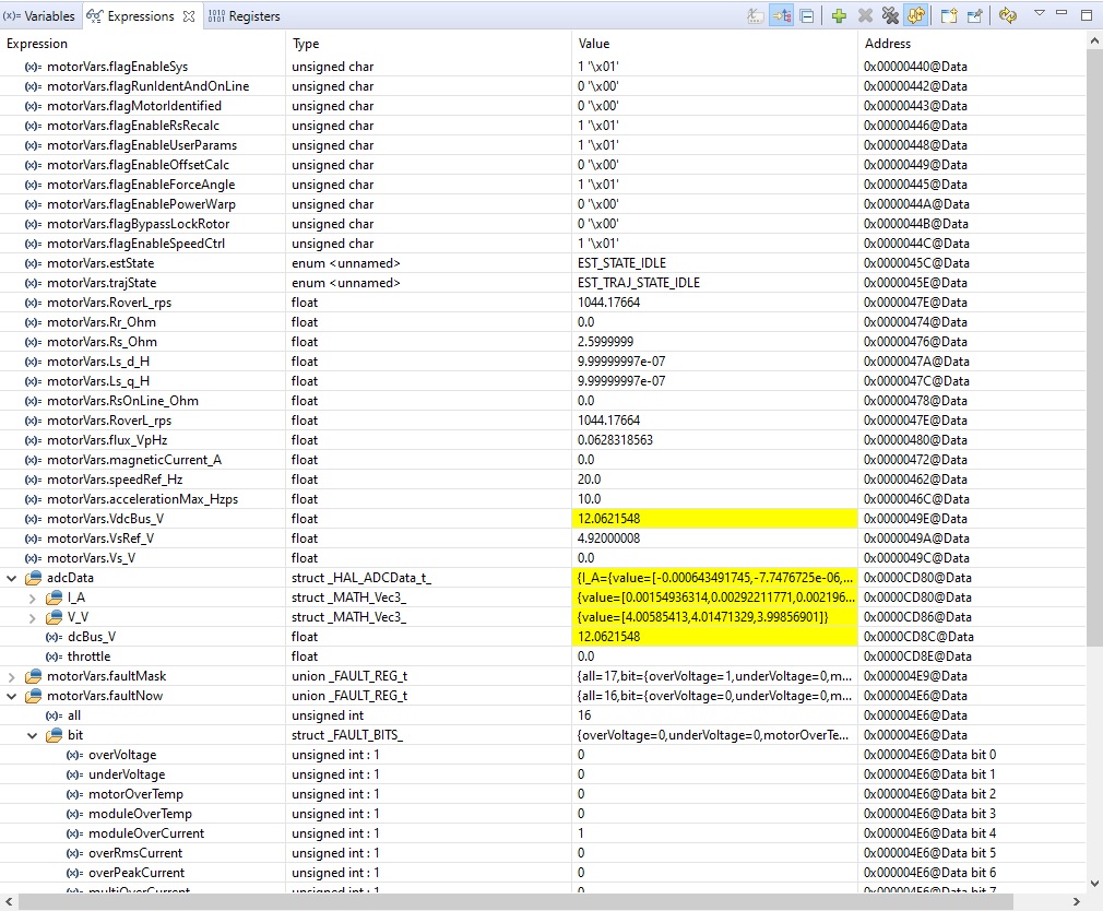
We have recently swapped R10, R11, and R12 out from 0.007 to 0.3 which should now be producing an ADC full scale current of 1.000A. However, when we run lab 5 and enable run an over current fault is triggered right away. The software current max is set to 0.6A and we are not seeing the power supply ever providing any current.
We are running a 12V motor and to get better BEMF resolution we swapped out R1, R2, R3, and R28 with 16.9K to achieve a new ADC full scale voltage of 14.476.
Any ideas why we would be seeing the over current fault?
#ifndef USER_H
#define USER_H

//! \file   solutions/boostxl_drv8320rs/f28004x/drivers/user.h
//! \brief  Contains the user related definitions
//!


// **************************************************************************
// the includes

// modules
#include "userParams.h"

//!
//!
//! \defgroup USER USER
//!
//@{


#ifdef __cplusplus
extern "C" {
#endif


// **************************************************************************
// the defines
#define BOOSTX_to_J1_J2     0
#define BOOSTX_to_J5_J6     1

#define BOOST_to_LPD        BOOSTX_to_J1_J2
//#define BOOST_to_LPD        BOOSTX_to_J5_J6

//! \brief Defines the nominal DC bus voltage, V
//!
#define USER_NOMINAL_DC_BUS_VOLTAGE_V         ((float32_t)(12.3))


//! \brief Defines the maximum voltage at the AD converter
//!        full scale voltage of AD converter
//#define USER_ADC_FULL_SCALE_VOLTAGE_V         ((float32_t)(57.528))
#define USER_ADC_FULL_SCALE_VOLTAGE_V         ((float32_t)(14.476))  //Chage R1, R2, R3, R28 from 82.0K --> 16.9K


//! \brief Defines the maximum current at the AD converter
//!        BOARD_BSXL8320RS_REVA, Gain=12
//#define USER_ADC_FULL_SCALE_CURRENT_A         ((float32_t)(42.843))
//BOARD_BSXL8320RS_REVA, Gain=12
//#define USER_ADC_FULL_SCALE_CURRENT_A         ((float32_t)(0.750))  //Change Shunt Ressitors R10, R11, R12 from 0.007 --> 0.4
#define USER_ADC_FULL_SCALE_CURRENT_A         ((float32_t)(1.000))  //Change Shunt Ressitors R10, R11, R12 from 0.007 --> 0.3

//! \brief Defines the analog voltage filter pole location, Hz
//!
#define USER_VOLTAGE_FILTER_POLE_Hz           ((float32_t)(414.25))


//! \brief ADC current offsets for A, B, and C phases
//#define IA_OFFSET_A    (-21.87679670)        // ~=0.5*USER_ADC_FULL_SCALE_CURRENT_A
//#define IB_OFFSET_A    (-21.57054520)        // ~=0.5*USER_ADC_FULL_SCALE_CURRENT_A
//#define IC_OFFSET_A    (-21.98300740)        // ~=0.5*USER_ADC_FULL_SCALE_CURRENT_A

#define IA_OFFSET_A    (-0.51097733)        // ~=0.5*USER_ADC_FULL_SCALE_CURRENT_A
#define IB_OFFSET_A    (-0.50316352)        // ~=0.5*USER_ADC_FULL_SCALE_CURRENT_A
#define IC_OFFSET_A    (-0.51292282)        // ~=0.5*USER_ADC_FULL_SCALE_CURRENT_A


//! \brief ADC voltage offsets for A, B, and C phases
#define VA_OFFSET_V    (4.07137489)    // ~=1.0
#define VB_OFFSET_V    (4.06430674)    // ~=1.0
#define VC_OFFSET_V    (4.07137489)    // ~=1.0

//! \brief Vbus used to calculate the voltage offsets A, B, and C
//!        =0.5*USER_NOMINAL_DC_BUS_VOLTAGE_V
#define VBUS_OFFSET_V  (0.5*USER_ADC_FULL_SCALE_VOLTAGE_V)


//! \brief Defines the maximum negative current to be applied in Id reference
//!
//#define USER_MAX_NEGATIVE_ID_REF_CURRENT_A    ((float32_t)(-2.0))
#define USER_MAX_NEGATIVE_ID_REF_CURRENT_A    ((float32_t)(-0.5 * USER_MOTOR_MAX_CURRENT)

//! \brief Defines the number of pwm clock ticks per isr clock tick
//!        Note: Valid values are from 1 to 15
#define USER_NUM_PWM_TICKS_PER_ISR_TICK        (2)  //1

//! \brief Defines the number of ISR clock ticks per current controller clock tick
//!
#define USER_NUM_ISR_TICKS_PER_CURRENT_TICK     (1)

//! \brief Defines the number of ISR clock ticks per speed controller clock tick
//!
#define USER_NUM_ISR_TICKS_PER_SPEED_TICK     (1) //10


//! \brief Defines the number of current sensors
//!
#define USER_NUM_CURRENT_SENSORS               (3)


//! \brief Defines the number of voltage sensors
//!
#define USER_NUM_VOLTAGE_SENSORS               (3)

//! \brief Defines the system maximum input frequency, MHz
//!
//#define USER_MAXIMUM_SCALE_FREQ_Hz    ((float32_t)(1000.0))
#define USER_MAXIMUM_SCALE_FREQ_Hz    ((float32_t)(210.0))  //(Frequency * 60)/3 pole pairs = 4,200 rpm

//! \brief Defines the system clock frequency, MHz
//!
#define USER_SYSTEM_FREQ_MHz       ((float32_t)(100.0))


//! \brief Defines the Pulse Width Modulation (PWM) frequency, kHz
//!
//#define USER_PWM_FREQ_kHz          ((float32_t)(5.0))      //5KHz PWM frequency
//#define USER_PWM_FREQ_kHz          ((float32_t)(10.0))     //10KHz PWM frequency
//#define USER_PWM_FREQ_kHz          ((float32_t)(12.0))     //12KHz PWM frequency
//#define USER_PWM_FREQ_kHz          ((float32_t)(15.0))     //15KHz PWM frequency
#define USER_PWM_FREQ_kHz          ((float32_t)(50.0))       //20KHz PWM frequency //20

//! \brief Defines the Pulse Width Modulation (PWM) period, usec
//!
#define USER_PWM_PERIOD_usec    ((float32_t)1000.0/USER_PWM_FREQ_kHz)


//! \brief Defines the Interrupt Service Routine (ISR) frequency, Hz
//!
#define USER_ISR_FREQ_Hz        (USER_PWM_FREQ_kHz * (float32_t)1000.0 / (float32_t)USER_NUM_PWM_TICKS_PER_ISR_TICK)


//! \brief Defines the Interrupt Service Routine (ISR) period, usec
//!
#define USER_ISR_PERIOD_usec    (USER_PWM_PERIOD_usec * (float32_t)USER_NUM_PWM_TICKS_PER_ISR_TICK)


#ifdef _VSF_EN_
//! \brief Defines the timer frequency for estimator, kHz
//!
#define USER_EST_FREQ_kHz       ((float32_t)(20.0))


//! \brief Defines the timer frequency for estimator, Hz
//!
#define USER_EST_FREQ_Hz        (USER_EST_FREQ_kHz * (float32_t)1000.0)


//! \brief Defines the Interrupt Service Routine (ISR) period, usec
//!
#define USER_EST_PERIOD_usec    ((float32_t)1000000.0/USER_EST_FREQ_Hz)


//! \brief Defines the timer frequency for controller, Hz
//!
#define USER_CTRL_FREQ_Hz        (USER_EST_FREQ_Hz)


//! \brief Defines the controller execution period, usec
//!
#define USER_CTRL_PERIOD_usec   (USER_EST_PERIOD_usec)


//! \brief Defines the controller execution period, sec
//!
#define USER_CTRL_PERIOD_sec    ((float32_t)USER_CTRL_PERIOD_usec/(float32_t)1000000.0)


//! \brief Defines the timer frequency for trajectory, Hz
//!
#define USER_TRAJ_FREQ_Hz       (USER_EST_FREQ_Hz)
#else

//! \brief Defines the timer frequency for estimator, kHz
//!
#define USER_EST_FREQ_Hz        (USER_ISR_FREQ_Hz)


//! \brief Defines the Interrupt Service Routine (ISR) period, usec
//!
#define USER_EST_PERIOD_usec    (USER_ISR_PERIOD_usec)


//! \brief Defines the timer frequency for controller, Hz
//!
#define USER_CTRL_FREQ_Hz        (USER_ISR_FREQ_Hz)


//! \brief Defines the controller execution period, usec
//!
#define USER_CTRL_PERIOD_usec   (USER_ISR_PERIOD_usec)


//! \brief Defines the controller execution period, sec
//!
#define USER_CTRL_PERIOD_sec    ((float32_t)USER_CTRL_PERIOD_usec/(float32_t)1000000.0)

//! \brief Defines the timer frequency for trajectory, Hz
//!
#define USER_TRAJ_FREQ_Hz       (USER_ISR_FREQ_Hz)
#endif  // _VPF_EN_


//! \brief Defines the direct voltage (Vd) scale factor
//!
#define USER_VD_SF                 ((float32_t)(0.95))


//! \brief Defines the voltage scale factor for the system
//!
#define USER_VOLTAGE_SF               (USER_ADC_FULL_SCALE_VOLTAGE_V / (float32_t)4096.0)            // 12 bit ADC, 2^12 = 4096
#define USER_DCBUS_VOLTAGE_SF         (USER_ADC_FULL_SCALE_DCBUS_VOLTAGE_V / (float32_t)4096.0)      // 12 bit ADC, 2^12 = 4096

//! \brief Defines the current scale factor for the system
//!
#define USER_CURRENT_SF               (USER_ADC_FULL_SCALE_CURRENT_A / (float32_t)4096.0)    // 12 bit ADC, 2^12 = 4096


//! \brief Defines the pole location for the DC bus filter, rad/sec
//!
#define USER_DCBUS_POLE_rps            ((float32_t)(100.0))


//! \brief Defines the pole location for the voltage and current offset estimation, rad/s
//!
#define USER_OFFSET_POLE_rps            ((float32_t)(20.0))


//! \brief Defines the pole location for the speed control filter, rad/sec
//!
#define USER_SPEED_POLE_rps        ((float32_t)(100.0))


//! \brief Defines the analog voltage filter pole location, rad/s
//!
#define USER_VOLTAGE_FILTER_POLE_rps  (MATH_TWO_PI * USER_VOLTAGE_FILTER_POLE_Hz)

//#define USER_MAX_VS_MAG_PU            (0.66)
//#define USER_MAX_VS_MAG_PU            (0.57)
#define USER_MAX_VS_MAG_PU              (0.5)


//! \brief Defines the reference Vs magnitude in per units allowed
//! \      Set the value equal from 0.5 to 0.95 of the maximum Vs magnitude
#define USER_VS_REF_MAG_PU              ((float32_t)(0.8) * USER_MAX_VS_MAG_PU)


//! \brief Defines the R/L excitation frequency, Hz
//!
#define USER_R_OVER_L_EXC_FREQ_Hz       ((float32_t)(300.0))


//! \brief Defines the R/L Kp scale factor, pu
//!        Kp used during R/L is USER_R_OVER_L_KP_SF *
//!        USER_NOMINAL_DC_BUS_VOLTAGE_V / USER_MOTOR_MAX_CURRENT_A;
#define USER_R_OVER_L_KP_SF        ((float32_t)(0.02))


//! \brief Defines maximum acceleration for the estimation speed profiles, Hz/sec
//!
#define USER_MAX_ACCEL_Hzps        ((float32_t)(2.0))


//! \brief Defines the IdRated delta to use during estimation
//!
#define USER_IDRATED_DELTA_A       ((float32_t)(0.0001))


//! \brief Defines the forced angle frequency, Hz
//!
#define USER_FORCE_ANGLE_FREQ_Hz            ((float32_t)(1.0))


//! \brief Defines the fraction of IdRated to use during inductance estimation
//!
#define USER_IDRATED_FRACTION_FOR_L_IDENT    ((float32_t)(0.5))


//! \brief Defines the fraction of SpeedMax to use during inductance estimation
//!
#define USER_SPEEDMAX_FRACTION_FOR_L_IDENT  ((float32_t)(1.0))


//! \brief Defines the Power Warp gain for computing Id reference
//!        If motor parameters are known, set this gain to:
//!        USER_PW_GAIN = SQRT(1.0 + USER_MOTOR_Rr_Ohm / USER_MOTOR_Rs_Ohm)
//!
#define USER_PW_GAIN                        ((float32_t)(1.0))

//! \brief A flag to bypass motor identification (1/0 : true/false)
//!
#define USER_BYPASS_MOTOR_ID       (1)    // No motor parameters identification
//#define USER_BYPASS_MOTOR_ID     (0)    // Do motor parameters identification

#define USER_ENABLE_MOTOR_ID        0
#define USER_DISABLE_MOTOR_ID       1


//! brief Define the Kp gain for Field Weakening Control
#define USER_FWC_KP                 0.05

//! brief Define the Ki gain for Field Weakening Control
#define USER_FWC_KI                 0.0002

//! brief Define the maximum current vector angle for Field Weakening Control
#define USER_FWC_MAX_ANGLE          (float32_t)(-75.0)                              // degree
#define USER_FWC_MAX_ANGLE_RAD      USER_FWC_MAX_ANGLE*MATH_PI/((float32_t)(180.0))   // rad

//! brief Define the minimum current vector angle for Field Weakening Control
#define USER_FWC_MIN_ANGLE          (float32_t)(0.0)                                // degree
#define USER_FWC_MIN_ANGLE_RAD      USER_FWC_MIN_ANGLE*MATH_PI/((float32_t)(180.0))   // rad

//============================================================================================
// Motor defines

#define OuterReef                  301

#define USER_MOTOR OuterReef

#if (USER_MOTOR == OuterReef)
#define USER_MOTOR_TYPE                   MOTOR_TYPE_PM
#define USER_MOTOR_NUM_POLE_PAIRS         (3)
#define USER_MOTOR_Rr_Ohm                 (2.6)
#define USER_MOTOR_Rs_Ohm                 (2.6)
#define USER_MOTOR_Ls_d_H                 (0.00249)
#define USER_MOTOR_Ls_q_H                 (0.00249)
#define USER_MOTOR_RATED_FLUX_VpHz        (0.250)
#define USER_MOTOR_MAGNETIZING_CURRENT_A  (0.0002)
#define USER_MOTOR_RES_EST_CURRENT_A      (0.1)
#define USER_MOTOR_IND_EST_CURRENT_A      (-0.1)
#define USER_MOTOR_MAX_CURRENT_A          (0.6)
#define USER_MOTOR_FLUX_EXC_FREQ_Hz       (20.0)

// Number of lines on the motor's quadrature encoder
#define USER_MOTOR_NUM_ENC_SLOTS          (1000)

#define USER_MOTOR_FREQ_MIN_HZ             (5.0)           // Hz
#define USER_MOTOR_FREQ_MAX_HZ            (210.0)         // Hz

#define USER_MOTOR_FREQ_LOW_HZ            (10.0)          // Hz
#define USER_MOTOR_FREQ_HIGH_HZ           (200.0)         // Hz
#define USER_MOTOR_VOLT_MIN_V             (9.0)           // Volt
#define USER_MOTOR_VOLT_MAX_V             (14.476)          // Volt

#else
#error No motor type specified
#endif


//! \brief Defines the maximum current slope for Id trajectory
//!
#define USER_MAX_CURRENT_DELTA_A        (USER_MOTOR_RES_EST_CURRENT_A / USER_ISR_FREQ_Hz)


//! \brief Defines the maximum current slope for Id trajectory during power warp mode
//!
#define USER_MAX_CURRENT_DELTA_PW_A    (0.3 * USER_MOTOR_RES_EST_CURRENT_A / USER_ISR_FREQ_Hz)


#ifndef USER_MOTOR
#error Motor type is not defined in user.h
#endif

#ifndef USER_MOTOR_TYPE
#error The motor type is not defined in user.h
#endif

#ifndef USER_MOTOR_NUM_POLE_PAIRS
#error Number of motor pole pairs is not defined in user.h
#endif

#ifndef USER_MOTOR_Rr_Ohm
#error The rotor resistance is not defined in user.h
#endif

#ifndef USER_MOTOR_Rs_Ohm
#error The stator resistance is not defined in user.h
#endif

#ifndef USER_MOTOR_Ls_d_H
#error The direct stator inductance is not defined in user.h
#endif

#ifndef USER_MOTOR_Ls_q_H
#error The quadrature stator inductance is not defined in user.h
#endif

#ifndef USER_MOTOR_RATED_FLUX_VpHz
#error The rated flux of motor is not defined in user.h
#endif

#ifndef USER_MOTOR_MAGNETIZING_CURRENT_A
#error The magnetizing current is not defined in user.h
#endif

#ifndef USER_MOTOR_RES_EST_CURRENT_A
#error The resistance estimation current is not defined in user.h
#endif

#ifndef USER_MOTOR_IND_EST_CURRENT_A
#error The inductance estimation current is not defined in user.h
#endif

#ifndef USER_MOTOR_MAX_CURRENT_A
#error The maximum current is not defined in user.h
#endif

#ifndef USER_MOTOR_FLUX_EXC_FREQ_Hz
#error The flux excitation frequency is not defined in user.h
#endif

#if ((USER_NUM_CURRENT_SENSORS < 2) || (USER_NUM_CURRENT_SENSORS > 3))
#error The number of current sensors must be 2 or 3
#endif

#if (USER_NUM_VOLTAGE_SENSORS != 3)
#error The number of voltage sensors must be 3
#endif


// **************************************************************************
// the typedefs


// **************************************************************************
// the globals


// **************************************************************************
// the functions

//! \brief      Sets the user parameter values
//! \param[in]  pUserParams  The pointer to the user param structure
extern void USER_setParams(USER_Params *pUserParams);


//! \brief      Sets the private user parameter values
//! \param[in]  pUserParams  The pointer to the user param structure
extern void USER_setParams_priv(USER_Params *pUserParams);


//! \brief      Sets the private user parameter values
//! \param[in]  pUserParams  The pointer to the user param structure
extern void cla_USER_setParams_priv(USER_Params *pUserParams);


#ifdef __cplusplus
}
#endif // extern "C"

//@}  // ingroup
#endif // end of USER_H definition
