This thread has been locked.

If you have a related question, please click the "Ask a related question" button in the top right corner. The newly created question will be automatically linked to this question.

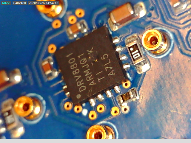
DRV8801: Blowing up/holes appearing on the OC

Part Number: DRV8801

We have seen some DRV8801 'blow up' or show this hole on top of them. This image has been taken with a USB Microscope.

I am wondering if anybody has seen this before and/or knows what could be causing it. 

We have a few of them like this, and they always blow up in exactly the same location. 

We have been using them in this application for about 6 years now, and noticed this for the first time. 

In terms of configuration, we have: 64 of these connected on a PCB in an 8x8 array, driving various motors. 

The setup runs at 28V, and drives around 2A for pulses that are about 100ms long.

A 5 second period may see up to 8 of those pulses, but there is normally a minimum of 30 second gap between those 'on 5 seconds'. More normally, the gap is several minutes. 

Is this a thermal issue? We know that the DRV8801 has a built-in thermal cut off, so should hopefully cut off things before this happens, but obviously, you never know. 

Keen to hear your thoughts/ideas. 

  • Hello Sami,

    Thank you for posting to the motor driver forum.

    To better understand what is happening I have a few questions for you:

    • You mention that there are multiple devices in one PCB. Did every device get damage in one PCB or just a few?
    • Was this issue observed across various other units?
    • Has the PCB layout design been updated recently?
    • Is the damage to the device happening during the 5 second period of high current pulses or is it more random? 
    • Can you share with me part of your schematic and layout (at least the part showing the driver and output stage)? you can share with me via private message if you don't want to share publicly.

    There could be multiple things causing the device damage. There can be a short somewhere in the PCB causing large amount of current to go through the driver. There can also be sufficiently large current transients at the output that last shorter than the over-current protection (OCP) deglitch time (3µs) which can damage the device. Determining if this is the case will require to look at the current waveform when the motor is operating at maximum current. Are you able to obtain this information? If so, it would good us a good indication that high current transients is causing the drivers to get damaged.


    The DRV8801 has over-temperature shutdown protection which disables the outputs when the current exceeds 175C. However, there is some deglitch time before the fault is registered and the outputs disabled. If the temperature rises very fast, the driver might register the fault until the temperature is high enough to cause damage to the device. 

  • Hi Pablo,

    Thank you very much for coming back to me. 

    I will answer your questions below:

    • You mention that there are multiple devices in one PCB. Did every device get damage in one PCB or just a few? > No, just a few. Out of 64, the maximum we saw get damaged was around 10. We have made around 30 odd of these boards so far, and the problem was only seen on 2. The other board had about 5 of these damaged out of 64. 
    • Was this issue observed across various other units? 2 out of around 30. 
    • Has the PCB layout design been updated recently? The latest revision is around 18 months old, though the particular part of circuit hasn't changed much in about 5 years. 
    • Is the damage to the device happening during the 5 second period of high current pulses or is it more random? > we are not sure what point the damage happened. We noticed it when we found that the circuits were not working (they are very embedded into a design, so normally hidden from a visual point of view), and when we explored, we found the visual mark I have put in the photo. 
    • Can you share with me part of your schematic and layout (at least the part showing the driver and output stage)? you can share with me via private message if you don't want to share publicly. > I will send this to you separately. 

    In terms of an image, here is a plot that shows both the current measured (using a Fluke i30 current probe) as well as the VPropI going into a 0.1 Ohm resistor. 

    The red is Vpropi, while the blue shows the current going in. 

    This is normally the maximum current that goes in. Being at 0.2V means it is drawing around 2A (1A = 100mV). 

    I will separately send you the circuit diagram. 

    Best regards,

    Sami

  • Just thinking more about current surges, just so you know, we have an inductive load in front of these ICs.

    They normally have resistance around 12Ohms. 

    They will sometimes fail short circuit, but in those cases, the DRV8801 is very happy to send us a FAULT signal back and as far as we are aware, does not try and drive into a short circuit. 

  • Hi Sami,

    Thank you for providing the information.

    Since you already sent me some documents you don't want to share in the forum, I will move this discussion privately. You can still reply to this post if there is any information you wish to share publicly. 

  • Hi Pablo,

    Thank you very much. 

    Best regards,

    Sami Mughal

  • For the purpose of anybody else interested in this problem:

    - The circuit was correct as per the application notes, so not a problem.

    - The thermals were correct too (i.e. it wasn't getting too hot)

    - We believe the problem could have come from an ESD event near the device. We have since identified the source, and looking to fix the problem.