This thread has been locked.

If you have a related question, please click the "Ask a related question" button in the top right corner. The newly created question will be automatically linked to this question.

DRV8323R: Setting hall inputs to lock the motor

Part Number: DRV8323R

Hi Team,

The customer would like to confirm if it is possible to set hall inputs so that the motor locks instead of the motor running when using 1x PWM mode ( SPI only )
To prevent the coils from getting too hot, the current is limited to a low value.

So that they don't need an extra magnetic brake to block the motor in some circumstances.

Please let me know your inputs and if you have other questions with the customer.

Thanks,

Jonathan

  • Hello Jonathan,

    I'd just like to confirm that the customer's use case and problem. The motor is running in 1x PWM mode, and they would like to try and stop the motor rapidly? In addition, they are currently trying to stop the motor quickly by overriding the actual the hall inputs, which will stop the motor (most likely by triggering an error)?

    Best,

    -Cole

  • Hi Cole,

    Thank you for your support in this thread.
    Let me share this question you have to the customer and I will get back for an update.

    Regards,

    Jonathan

  • Hi Cole,

    I got an update from the customer below:

    The customer wants to be able to break the motor when the motor is not running, thats all.
    For braking, while the engine is running we use a 4-quadrant control.
    It is for a cart to prevent if it is stationary does not roll away, that is for short times.

    Let me know your inputs.

    Regards,

    Jonathan

  • Hey Jonathan,

    Thank for the follow up.

    Unfortunately, there's no inherent function, IP, or pin that allows the user to Brake the motor when it is not running. The nBRAKE pin (or BRAKE bit field) simply turns on all the low-side MOSFETs which is only really used when the motor is spinning and it needs to slow down to a stop. Turning on all 3 low side MOSFETS will not oppose external force to the rotor.

    In addition, the device cannot detect the rotor spinning on its own when no gates are being driven. This leads to a system problem with two facets:

    • How to detect rotor movement
    • Coming up with an algorithm that will force current to either resist and hold or counter-act the force being applied

    How to detect rotor movement:

    Like commutation, you either do this will sensors or sensorless. BEMF comparators can detect changes according to some threshold but BEMF is dependent on speed of rotation so the Kt comes into play as there will be some delay before the control can react.

    Hall sensors or encoders will help see the rotation "instantly", compared to BEMF. Seeing that DRV8323R is used, I assume there was a need to drive this sensorlessly. Alternatively, you could blindly enact a brake algorithm whenever the motor is "idle" but be prepared that such an algorithm will use current and switch (or turn on the) the FETs, which burns power in a way that does not directly contribute to spinning the motor.

    Coming up with an algorithm:

    Luckily, 6x or 3x PWM can help here as driving a high and low side that cause current to flow into the motor, will result in rotor to align into some position. As long as there is a current through the stator windings, the rotor will attempt to align the field produced by the stator. As long as that field results in a force that is greater than the external force, the rotor (or cart wheels) won't move.

    Alternatively, drive the motor in the opposite direction of the force can help by moving the force vector an a completely opposite direction of the external force, which would eventually result in net zero force. Though is very tricky to program.

    Comments about the feature:

    We've heard this kind of operation time and time again from other users and we want to accommodate their requests. While none of the current generation  parts have this feature, we know that a future generation will.

    Best,

    -Cole

  • Hello Cole,

    I got an update from the customer and to make sure I will not miss any, I will just paste the response below:

    "You comments about the feature:

    We've heard this kind of operation time and time again from other users and we want to accommodate their requests. While none of the current generation parts have this feature, we know that a future generation will.

    For the first installations we can place an extra magnetic brake on the motor, but for the future it would be nice if footprint is the same as the current IC.

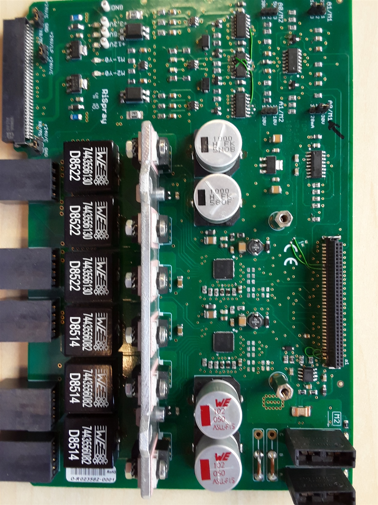
    I have added a photo of the proto pcb with twice the DRV8323RS, so we can put the new IC on the same PCB only SPI program extension:


    Then we can cancel the extra magnetic brake in the future on the same PCB, that would be nice."

    Please let me know your input.

    Regards,

    Jonathan

  • Hey Jonathan,

    Thanks for the update. I'll pass this feedback to team responsible for defining the future generations of parts. For obvious non-disclosure reasons, I can't really say much more at this time.

    For now, I think the thread's resolved, please take moment to click the "this resolved my issue" button on the other post so other users can find it a bit easier.

    Best,

    -Cole

    P.s. Would always recommend pouring GND on top and bottom layers; try to go "via, cap, then pin" if the nearby components are used for decoupling; and 10mils with 1oz copper pour for every 1A through the trace. Layout App note: https://www.ti.com/lit/an/slva959a/slva959a.pdf