This thread has been locked.

If you have a related question, please click the "Ask a related question" button in the top right corner. The newly created question will be automatically linked to this question.

DRV8350: drv8350 not work and the Vgls and GLX is short

Part Number: DRV8350

hello:

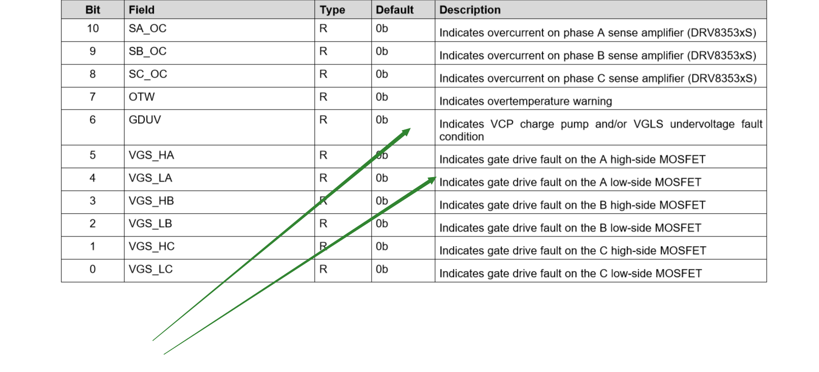
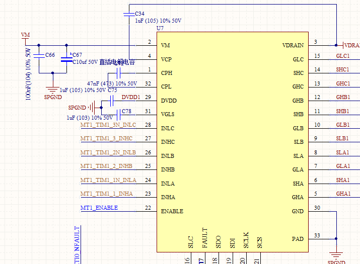
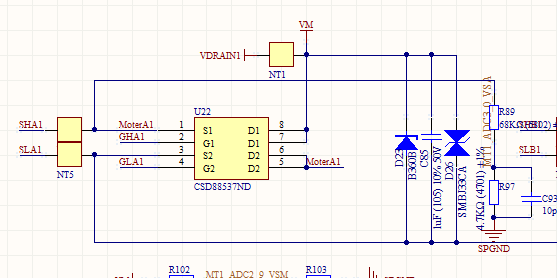
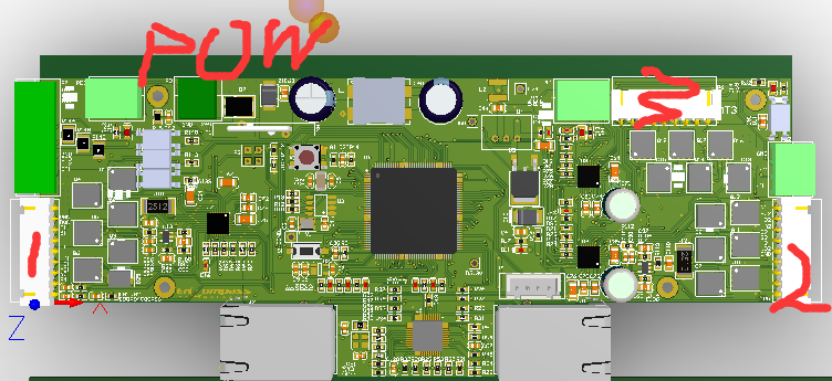
      We developed a three-phase motor drive board ,using chip DRV8350Rs.When we do quick start stop(300ms) experiment. Motor 2 and 3 didn't work and the capacitance of the power VM is burned. It senms like that  the chip didn‘t work and report nfault.It is strange that  the motor 1 works excellently while the diagram of them is same.After change some capacitance  and diode , we found that the VGLS and GLX is internally short-ciruit when the Drv8350 report fault like the green arrrow indicated in the picture.

I wonder that why the motor 2 and 3 can't work like motor 1 and it is the same reason that the VGLS and GLX is short and motor can't with heating capacitance.

pleast check the diagram and fault report.

  • Hello ;

    Thanks for posting on the Motor Drivers Forum! Let me give you a full response tomorrow, 9/10/20 CDT.

    My first impressions lean towards layout. Can you confirm the locations of the internal short by taking a Digital Multi-meter and using the impedance test between the two pins you think are internally shorted?

    Gate Drive faults on Low-side A means that the GLA would be shorted to GND, or VGLS. Where GDUV means that VGLS or VCP is shorted to GND, VDRAIN, or VM.

    The reason I think that layout is the problem relates to what you've told me so far. I am assuming you:

    • Kept the schematic the same between Motor 1, 2, and 3 (as you've mentioned)
    • Used the same group of devices from the same tube or reel
    • Used very similar motors for 1, 2, and 3 that require similar voltage and power

    The only differences are:

    • layout between Motors 1, 2, and 3
      • Layout of Motor 1 does look much better. More area devoted to phase and FET nodes and the gate paths look much more symmetrical 
    • Both DRV8350's for Motor 2, and 3 were damaged before driving the motor, and the DRV8350 was not
      • This is unlikely, but can test this by desoldering the DRV8350 used for motor 1, soldering it in place of motor 2 or motor 3, and repeating the experiment. If the motor runs in motor 2 or 3, then the devices were at fault
    • Something in the sensing path for Motor 2 and 3 were damaged or different which then contributed to incorrect commutation  
    • This is also unlikely as we have plenty of protection features that will attempt to stop incorrect commutation

    Best,

    -Cole

  • hello Cole,

            thank you for your valuable suggestion .

            The short location is pin 31 VGLS and pin15 GLC of all damaged drv8350.

             Yes,  I also think the gate path of MT1 is better.But because of the sides of board ,I have no space  to make its area bigger.So

    how I can improve the 2 and 3  to make it perform like 1?

    Thank you 

    Shengzhong

  • hello Cole :

          we have tried  to exchange the chip  boto 1 ,2 and 3. The chip 1  moved to phase 2 or 3,the motor 2 and 3 all wili not work.

           AND I  found that there will be -3V (some time bigger) in SLC  occasionally. i thinks there must be some problem in the layout which caused this problem .Can you leave your email address and I send my pcb project to you .And then we can discuss way to solve it.

    best 

    shengzhong

  • Hello shengzhong,

    I have sent you a friend request with my email in the message, please contact me directly through email and we will close officially on this thread after we've taken a look at your board files.

    Thanks,

    -Cole