Dear Teams,
Have a nice day! I am helping my customer test DRV8833CEVM.
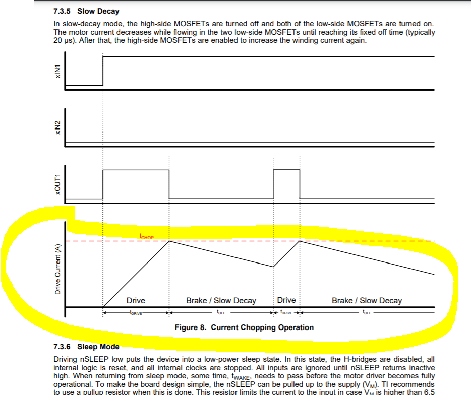
Could I ask the whether the "Stop" button is used for Fast Decay Mode or Slow Decay Mode?
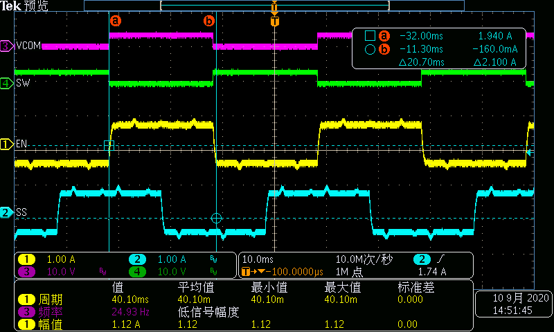
Secondly, how could I obtain driven current waveform shown in the following picture?
Lastly, what is the purpose of the "Slow Down" feature for the EVM? It is only for adjust the motor speed, but not the decay mode?
Thanks!
Dylan