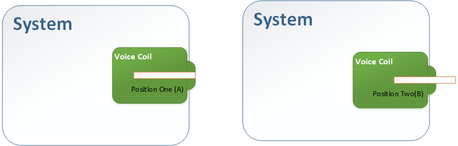
3. While the shaft in position (B), we need to change in voice coil shaft force
4. We need to move from position A to B and from B to A in full speed
5. we will repeat this cycle of movements
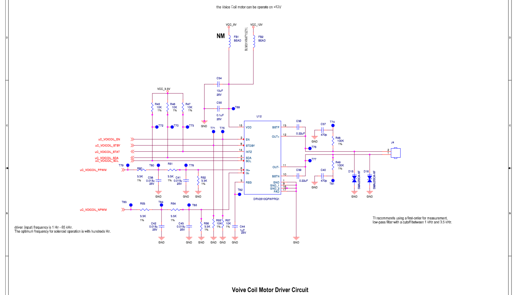
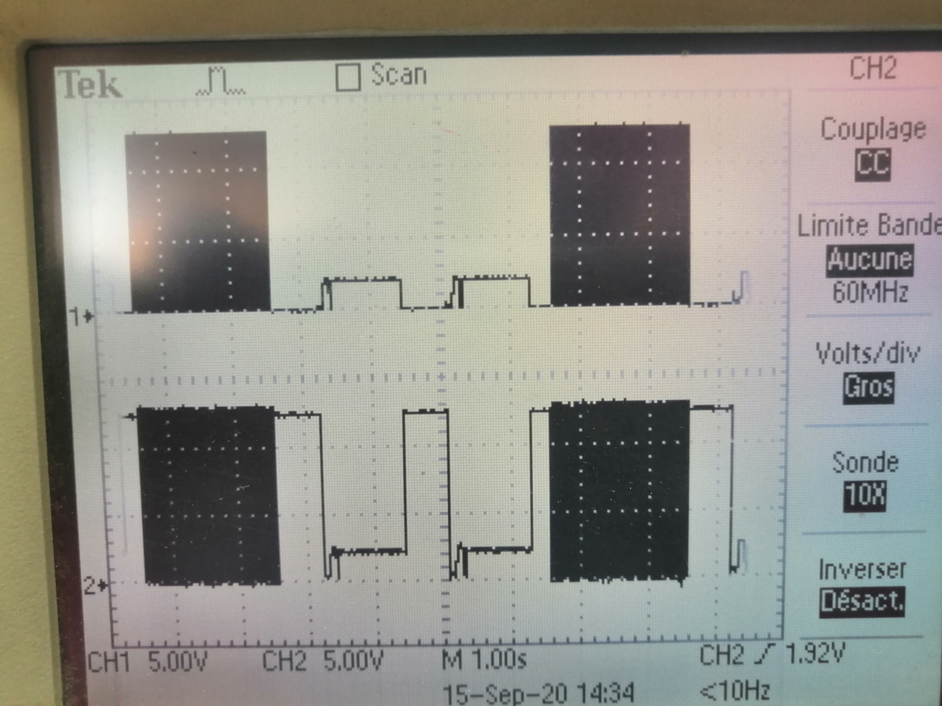
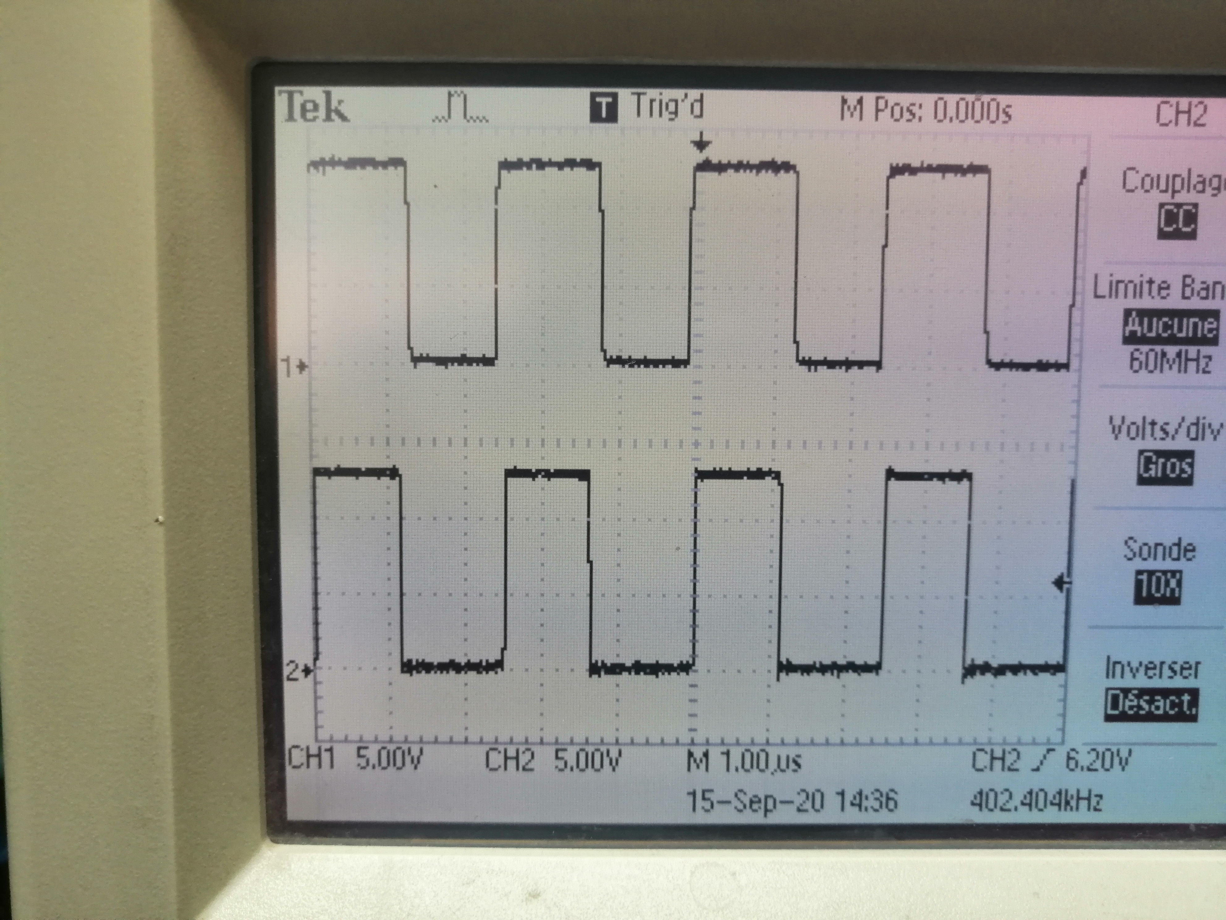
our problem is the above steps but results are different that the expected, where the voice coil shaft canot be energized for the specified time in the above steps. just less than 1 second. i test also through its evaluation kit and i got same results of our circuit schematic.
Any Help?. thanks in advance.